![]()
Welcome to the Retro Gadgets documentation!
Use the chapters on the left to navigate the contents of this document. If you have any requests or suggestions, talk to us on our Discord server!
If this is your first time here, check out the Getting Started page.
See also
Retro Gadgets uses Luau extensions over Lua 5.1 for the programming portion. For more information on all the features the language provides, check the following external links:
- Programming in Lua - the official Lua introduction to programming
- Lua 5.1 Reference Manual
- Luau extension syntax
- Luau extension library
- Retro Gadgets official YouTube channel (contains video tutorials)
Getting Started
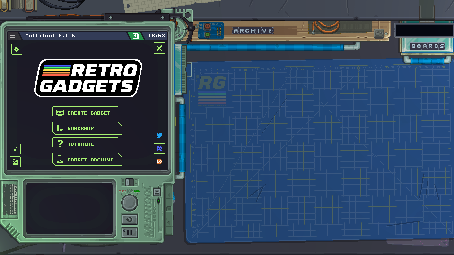
This is the initial view once you start Retro Gadgets. The rest of this document will explain to you the interface and the basics of how gadgets work, but if you want to learn in-depth programming techniques we recommend you check the gadgets under the Tutorial button to see how they were built.
The Gadget Archive button will take you to the folder in your computer where Retro Gadgets files are stored. This will be important for importing assets, creating new cutting mats, among other things.
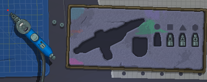
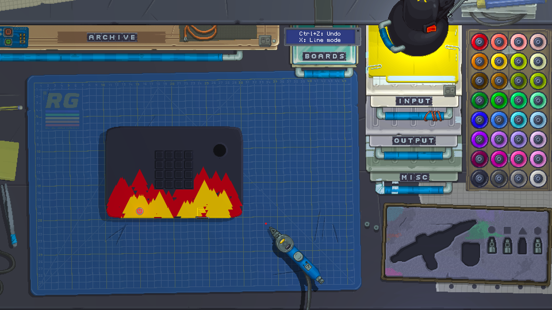
Your desk
Once you close the Multitool you will see an overhead view of your workbench and your tools. The main drawers and tools at your disposal are highlighted with blue handles.
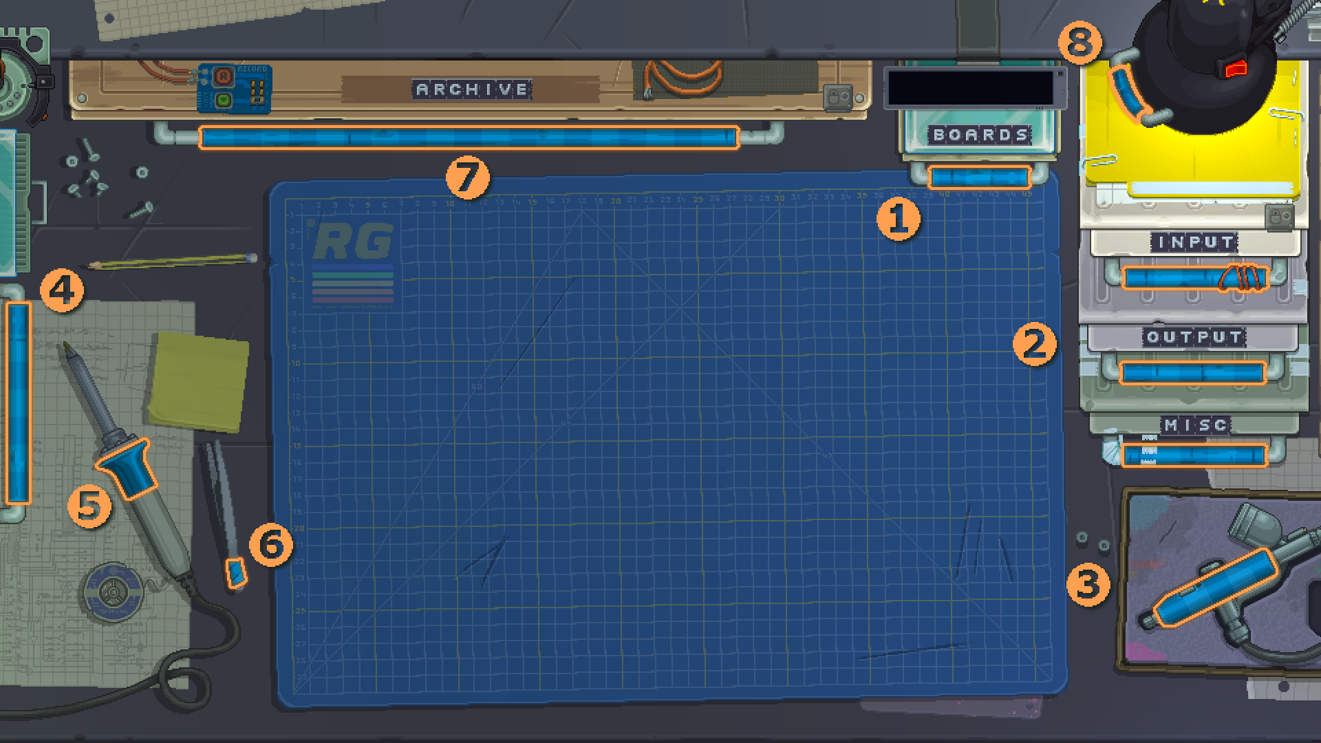
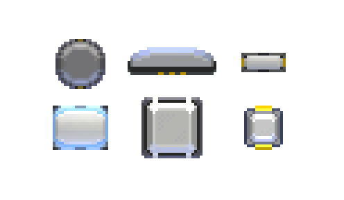
- Boards drawer - Inside this drawer are the parts with which you can build the base for your gadgets, giving them a shape.
- Inputs, Outputs and Misc - Each of these drawers contain their corresponding modules, which add functionality to your gadgets.
- Airbrush - Once you have a shell for your gadget, you can use this to paint it in a selection of colors.
- Multitool handle - This will open and close the Multitool, where you can edit your gadget, its assets and debug your code.
- Soldering iron - Using this tool you can join board parts together to form a bigger gadget, once you've placed them next to each other.
- Tweezers - This tool allows you to move stickers after they're placed down on your gadget.
- Archive - This drawer holds all the gadgets you've built or printed from the workshop, once you put them away from your desk. It also contains some example gadgets included with the game that you can play with, take apart and learn from.
- Desk lamp - No workbench is complete without a lamp to help you see your gadgets! You can use the handle to reposition it, turn it on and off with the switch, and even control it with the desk global methods.
Some of these drawers or tools will become inaccessible while a gadget is currently turned on, this will be indicated with a lock sign or a lid over them.
Once you've familiarized yourself with your tools, check out the FAQ and the Cookbook examples to get started building gadgets!
Minitool
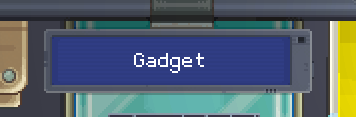
The Minitool is a pager-like device that sits atop your Boards drawer. It can give you information about the things you click in the game, such as the name of modules you select, and you can make it display your own messages from your gadget with the Minitool methods
Cutting Mats
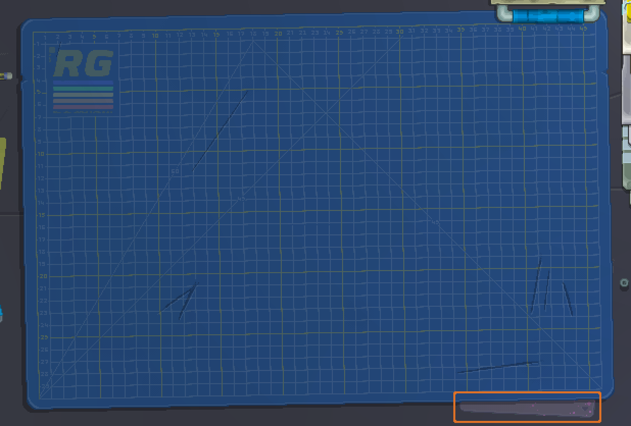
You start the game with a standard blue cutting mat with the Retro Gadgets logo. If you wish to change your cutting mat, you can go into Gadget Archive on the main menu and look into the CuttingMats folder. Inside that folder there is a README file which gives you instructions on creating your own mats and a Samples folder with some different mats ready to be used or modified.
Once you have some custom mats to put into the game, put them inside the Active folder in the cutting mats folder, restart your game, and click on the tab at the bottom-right corner of your mat, highlighted above in orange, to cycle between all active mats. Note this tab is only present if you have no gadgets currently placed onto your mat.
Another thing to note is how Steam Cloud backs up the Retro (Gadget Archive) folder, such that if you're trying to remove a file you must do it while the game is running so that the removed file syncs with Steam when you quit the game. Otherwise, if you remove a file while the game is not running, it will be restored by Steam Cloud when you launch the game again.
Recording Videos
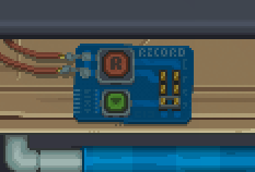
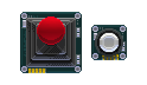
Above your Archive drawer, a small board lets you record your gadget creations into MP4 video files to share with others online. The large red button will start and stop a recording, while the smaller green button below it will open the recording settings, where you can also open the folder where your videos are stored after recording.
Multitool
The Multitool sits to the left of your workbench. It's used to edit your gadget and its assets, as well as serving as the game's main menu and interface.
Gadget view
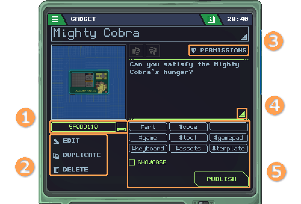
Once you start editing a gadget, this screen will appear.
- This is the ID of the gadget in your computer. Clicking it will open the folder where it's stored so you can access its
rgadgetfile. - The edit button brings you to the gadget's assets. Duplicate (or Jailbreak for gadgets downloaded from the Workshop) will make a new copy of the gadget and Delete will delete it.
- This button allows you to change the gadget's permissions.
- These triangle-shaped buttons allow you to edit the gadget's name and description.
- This section allows you to publish your finished gadget to the Workshop. The tags let you categorize your gadget and the "Showcase" flag will put it in the showcase list.
Permissions
To use Wi-Fi and Camera functions on each gadget, you need to grant it permissions. Otherwise, trying to make a web request or display a picture will result in an access denied error. To enable permissions, you need to edit the gadget and click on the Permissions button in the Multitool shown above.
Asset list
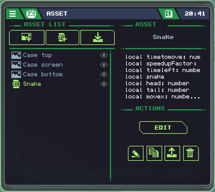
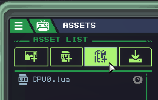
On this screen you can manage the assets contained in your gadget. The three buttons at the top, respectively:
- Allows you to create new SpriteSheets with the Sprite Editor
- Create new Code with the Code Editor
- And import an external asset from your computer.
To import assets into your gadget, they must be in the Import folder in your computer, which can be found by clicking the Gadget Archive button in the main menu.
For assets to be used within your gadget's code, you need to include a ROM module in your gadget.
Bottom screen
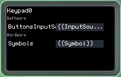
In the bottom screen of the Multitool, you can change different properties of each module you click on your gadget while the Multitool is open. At the top of this screen, you can also see the name each one of your gadget's modules has, in order to use them in your code.
The properties labeled as Software can either be changed here, for your gadget's initial state at power on, or be changed with code your gadget runs. Properties labeled Hardware can only be changed here. One such property is Symbol, which changes what is printed physically on a button.
Airbrush
The Airbrush tool allows you to paint gadget shells and modules. Once you click on it in the bottom right corner of your desk, the camera pans to present you with all the options such as colors and different nozzles. Like the other tools and drawers, the Airbrush is only available while your gadget is powered off, this is noted by the toolbox being closed with a lid while it's on.
Using the Airbrush
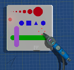
When the Airbrush is active, it will follow your cursor with a red marker indicating where your are pointing. This marker will change in shape and size depending on the nozzle, size and mode you are currently using.
To change the size of your brush, scroll up and down with your mouse wheel. The size will be indicated both by the red marker and by a number on the handle of the Airbrush. To change the nozzle shape, simply click on them in the Airbrush's tool box to pick them up. Pressing X will toggle between locking to horizontal and vertical line modes, before returning to regular freehand mode. You can hold down the left shift key to zoom into your gadget for precision. You can also press Ctrl-Z to undo each paint stroke.
To select a color for your Airbrush, simply click on an ink bottle on the right. You can click with the right mouse button to select a secondary color. This color will be used if you paint with the right button instead of the left button.
You can also use stickers as masks for painting over. By placing a stencil sticker on your gadget, painting over it, then removing the sticker with the tweezers, you'll note the shell won't be painted where the sticker was sitting.
Certain modules can be painted with the Airbrush by clicking directly on them, and some modules also have a secondary color that can be set. For example, painting the Keypad with the left click will paint the bezel around the buttons, while painting it with the right click will paint the buttons themselves.
Once you are done using the Airbrush, simply click on its empty spot in the tool box to put it away.
Sprite Editor
![]()
The Sprite Editor is where you can create and modify SpriteSheets for your gadgets.
Each of its tools will have more information and settings in the bottom screen of the Multitool as you click them.
 The brush allows you to draw pixels and lines.
 The fill bucket allows you to flood-fill or replace entire swaths of colors in your sprite or image.
 The shapes tool allows you to draw circles and squares.
 The selection tool allows you to select part of your images and move, flip or copy them.
 The eyedropper allows you to select colors from the image.
 In the settings you can change colors and opacities for the UI elements of the Sprite Editor, such as grids and background.
 The printer lets you print out stickers for your gadget's shell.
 The font tool allows you to create custom fonts to use when displaying text on video screens.
 This will display your cursor's current position in the image. If the mouse icon is enabled, the position will be in pixels relative to the whole SpriteSheet. If the grid below it is enabled, the position will show you the X and Y values of each whole sprite in your sheet.
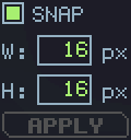 These W and H values will set the size of every sprite in your sheet, that is, by how many pixels to slice your entire sprite sheet into individual sprites. Width and height can be different values, but values that aren't powers of 2 will disable the SNAP setting which lets your zoomed view snap to each sprite in the editor.
Palettes
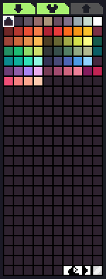
The palette will contain all the colors used in your sprite sheet. You can select colors to use with the editor's tools with the left mouse button for primary color and with the right mouse button for secondary or background color. The last entry in the palette, shown in the bottom right, is always transparent.
The down arrow in the top left allows you to load built-in palettes or palettes from other sprite sheets in your gadget's assets. The wrench next to it allows you to edit each color in your palette. Since palettes use indexed color, changing colors used in your sheet will change them across the whole image as well.
Fonts
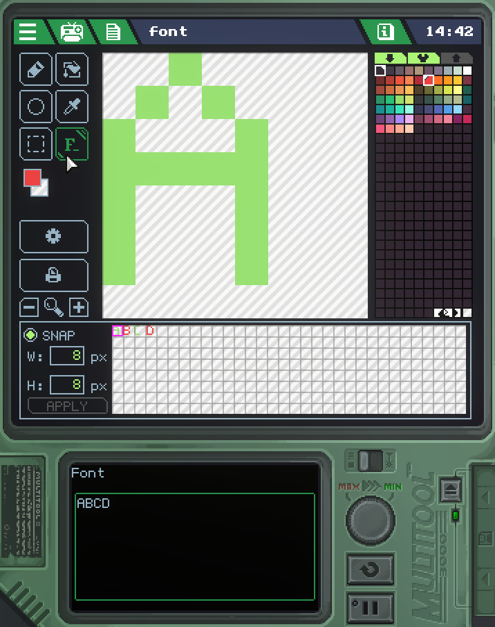
You can make a custom font by slicing your sprite sheet such that each sprite is one glyph (or character) of your desired font. Remember you can change the size of your sheet's sprites with the W and H values as explained above.
Once you have your sprites for every character you want to represent, use the "Font" tool. In the textbox that appears at the bottom, type the characters in the order they appear in your sheet, so that the game knows which sprite is what letter. Once all that is done, you can use this SpriteSheet in place of the default StandardFont when using DrawText.
Stickers
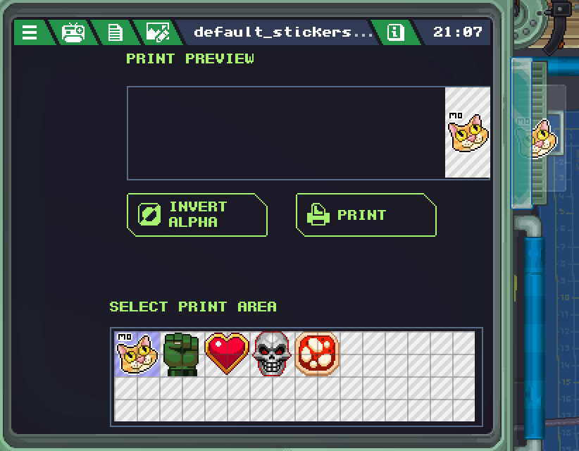
Stickers can be placed on your gadget's shell as decoration, or to be used as masks for painting with the airbrush spray. To print a sticker from your SpriteSheet, first select the area you want to print out at the bottom. You can use the Invert Alpha button to turn the image into a negative mask instead, and once you're ready you can press Print to turn the image into a sticker.
You can then drag the sticker onto your gadget to place it down, and from there you must use the tweezers on your desk to move or remove it from your gadget. To get rid of a sticker, simply drag it back into the printer output. If you don't immediately drag a new sticker out of the printer, you can continue printing more images onto the same sticker sheet.
Code Editor
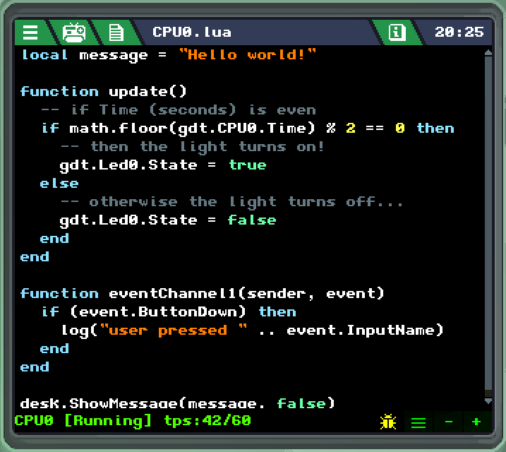
The Code Editor is where you can write the Lua code your gadget's CPU will run. If you're a beginner at programming and want to see some code examples, you can look in the Tutorial button on the main menu for a variety of built-in gadgets you can inspect and learn from.
At the bottom of the editor, there is a status bar that will tell the runtime state of your code while your gadget is on. It can show the performance of your gadget in "tps" (Ticks Per Second), or if your gadget has encountered an error. Errors are displayed in red and can be hovered over to show more information about what happened.
At the bottom-right there are 4 buttons, respectively:
- Debugging will show line numbers so you can click them to set breakpoints in your code to inspect it more closely. Your code will pause at the breakpoint until told to continue, and clicking the current running line will show you a stacktrace.
- Word wrap will wrap around lines that are too long horizontally to be displayed on the screen. When disabled, a horizontal scroll bar will be shown instead.
- Minus button will decrease the resolution of the code editor, meaning letters are bigger and less code will fit on screen at once.
- Plus button will increase the resolution of the code editor, meaning letters are smaller and more code will fit on screen at once.
Depending on your monitor's resolution, the minus and plus buttons may not have any effect.
To learn more about how to program in Retro Gadgets, see the Glossary and Code Structure pages.
Frequently Asked Questions
Here are some of the more frequently asked questions we've received, linking to different parts of this document where you can get more information. Be sure to also check out the cookbook examples if you haven't, as those can teach you some of the basic concepts of Retro Gadgets. If you still have any questions, feel free to ask in our Discord server!
How do I get started building a gadget?
We show how to build a gadget from scratch that takes button inputs and outputs sound in our Sound Board cookbook example. It also serves as teaching you the very basics to follow later cookbook examples.
Additionally, you can look at the built-in gadgets under the Tutorial button in the main menu to see how they were made.
The camera or the wi-fi modules don't work!
Check that your gadget permissions are set correctly. Additionally, there is currently no way to switch between camera sources in computers with multiple sources, so the game might not be detecting your webcam correctly.
I'm trying to use a function, but it seems to ask for the wrong number of arguments!
Check that you are using : (colon) for object methods, and . (period) for properties. Check out the glossary for more information on methods and properties.
How do I load assets to use in my code? GetAudioSample and GetSpriteSheet don't work!
Between the Next Fest demo and the Early Access release, some of the syntax was changed with new features and some supplemental material might not reflect that. To use assets currently, you must drag a ROM chip onto your gadget from the Misc drawer, and replace calls such as:
local sprites:SpriteSheet = GetSpriteSheet("filename.png")
with:
local sprites:SpriteSheet = gdt.ROM.User.SpriteSheets["filename.png"]
For built-in assets such as "StandardFont", replace User with System. For audio assets, replace SpriteSheets with AudioSamples. See the ROM page for more information.
How can I protect my gadget's assets or code from copying when I publish it into the Workshop?
You can include a SecurityChip in your gadget to lock its assets. Check out the module page for more information.
How do I tell what size a screen is?
A Screen module will have Width and Height properties that you can read to get the size of each individual screen. If you connect multiple screens to the same VideoChip, the drawing buffer grows in order to accommodate all the connected screens, so you can use the Width and Height properties of the VideoChip instead to get the full resolution of your combined screen. If you want to know what size each screen in the drawer is, that information is also in the Screen module's page in this document.
How do I make a code delay, or how do I make my code wait some time?
Since Retro Gadgets is aimed at being programmed like any other basic computer would need to be, you need to code everything from scratch. The CPU gives you a couple of time properties that allow you to do this.
First, understand your code runs in ticks. That means for each tick, your entire update() function will have run through in its entirety. Retro Gadgets aims to run at 60 ticks per second, that is your update() will run 60 times every second. This is fine for logic and for parsing inputs.
Second, we need a way to determine how much time has passed. We can do this by reading gdt.CPU0.Time to get the total time in seconds since the gadget has turned on, or gdt.CPU0.DeltaTime to get the time in seconds that passed since the last tick.
Say we want something to happen 2 seconds after a trigger, like a button. You could write it like so:
-- we start with an unset timer as nil, meaning null or unset
local timeToTrigger = nil
function update()
    if gdt.LedButton0.ButtonDown then
        -- we set the timer for 2 seconds from the current time
        timeToTrigger = gdt.CPU0.Time + 2
    end

    -- this if first checks if the timer is set, then if the time is right
    if timeToTrigger and gdt.CPU.Time >= timeToTrigger then
        timeToTrigger = nil
        -- this will execute once when the time is right
        -- and will not execute again since we unset the timer
        -- you can put your code to be triggered here
    end
end
There are other ways to keep track of time than individual timers however. If you want something to happen every half second, for example:
-- let's call our repeating timer "frames", meaning every half second we
-- advance one frame
local frameDuration = 0.5
-- this will keep track of DeltaTime
local deltaCounter = 0

function frame()
    -- this will get called every 0.5 seconds
end

function update()
    -- increase the counter by the CPU's DeltaTime
    deltaCounter += gdt.CPU0.DeltaTime

    -- we run a while loop for however many times the delta counter is greater
    -- than the duration of one frame, such that if for some reason the counter
    -- has gone past over one frame duration, we run our frame loop however many
    -- times necessary to keep the logic tied to the timer.
    while (deltaCounter >= frameDuration) do
        deltaCounter -= frameDuration
        frame()
    end
end
This last method is useful for repeating timers such as one to run a drum machine or a game's animation logic cycle.
How do I check collision between two sprites?
Like the delay question above, there is no built-in simple way to do this, and you have to make your own from scratch. The simplest type of collision checking you can write is called AABB collision, which checks if 2 rectangles are overlapping.
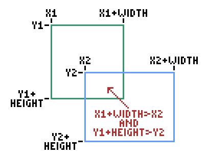
To tell if the two boxes are overlapping, you need to know the position of each box (X and Y), and their sizes (Width and Height). However you store these values depends on your own code. Then, it's a matter of comparing those values like such:
function is_colliding(x1, y1, w1, h1, x2, y2, w2, h2)
    return x1 < x2 + w2 and x1 + w1 > x2 and
        y1 < y2 + h2 and y1 + h1 > y2
end
...where x1 and y1 are the top-left coordinates of the first box, w1 and h1 are the width and height of the first box, x2 and y2 are the top-left coordinates of the second box, and w2 and h2 are the width and height of the second box. The function will return true if there is a collision between those coordinates, or false otherwise.
Controls
Gadget Building
| Grab a component | Left Mouse Button |
| Rotate grabbed component | Right Mouse Button while grabbing |
| Zoom | Left Shift |
Airbrush
| Pick main color | Left Mouse Button on a color jar |
| Pick secondary color | Right Mouse Button on a color jar |
| Spray with main color | Left Mouse Button |
| Spray with secondary color | Right Mouse Button |
| Cycle drawing modes (free, horizontal, vertical) | X |
| Alter the nozzle size | Mouse Wheel |
Code Editor
| Debug: next step | F1 |
| Debug: continue running | F2 |
APIs
Glossary
Here is a basic understanding of some of the terms used in RetroGadgets for handling modules and other functions. For a more in-depth overview, check out the official Lua document on Object-Oriented programming.
Objects
An object is an instantiation of a class. Each module in your gadget is an instance of their type of module, therefore they're objects. For example, LcdDisplay is a type of module for text LCD displays, but to refer to the first LCD display in your gadget specifically you use gdt.Lcd0. The name of each individual object on your gadget can be checked using the Multitool. All of your gadget's modules can be found inside gdt as a table.
Note that modules which can only appear once in your gadget, such as ROM and PowerButton won't have a number at the end of their names in the gdt table, for example gdt.ROM and gdt.PowerButton.
Properties
A property is a value that can be read or set in an object. For example, it can be used to check the current condition of a module, or modify it.
It should be called with object.property.
Examples:
gdt.Led0.State = gdt.LedButton0.ButtonState
This sets the state of a LED Led0 to be the same as the incoming state of the button LedButton0. What will happen is that the LED will turn on as long as the button is pressed down.
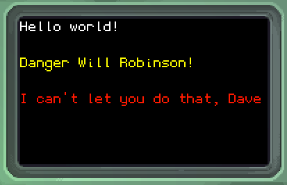
gdt.Lcd0.Text = "Hello world!"
This will set the text property of an LCD screen Lcd0 to the string "Hello world!", displaying it.
In this document:
description of the property
The name of the property is highlighted in bold. The type of that property is marked in red and links to an overview of the type. If the property can only be read, and not set, it will be marked as such to indicate it. If a type is surrounded by one of more {curly brackets}, that means that it's a table.
Methods
A method is a function which receives additional arguments to carry out a task.
Unless a method is determined to be a global method, it needs to be called in relation to a specific object. In order to do so, you must call it with object:method(argument). This way, with :, you are telling the function that what it expects to be the self argument is object.
Example:
gdt.AudioChip0:Play(sample, 1)
This will tell the AudioChip AudioChip0 to play a previously loaded sample sample on channel 1.
If a method is global, it can be called by itself, or if is static and part of a generic class, with a . like so: class.method(argument).
Example:
desk.SetLampState(true)
This will turn on the desk lamp.
In this document:
method( argument1 type, argument2 type ) type
description of the method
The name of the method is highlighted in bold. The arguments are shown between parentheses and each of them has a respective type they expect. If the method returns a value, the type it returns is marked at the end. If a type is surrounded by one of more {curly brackets}, that means that it's a table.
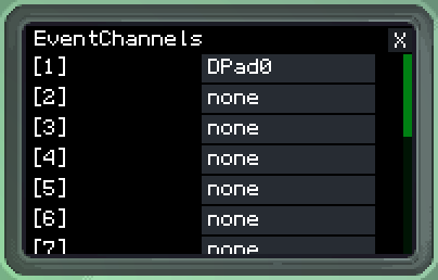
Events
An event is triggered by a module external to the CPU. For example the Wifi module triggers an event when a web request returns a response. To handle events, you must select the module that raises the event on your CPU's EventChannels and a specially named function eventChannelN, where N must be replaced by the number of your channel, will run when the event is triggered. The event channel function receives the module that triggered the event, and a table containing values pertaining to that event.
Example:
function eventChannel1(sender, event)
	log("got event " .. tostring(event) .. " from module " .. tostring(sender))
end
This function will handle incoming events on channel 1, once the module connected to that channel sends the CPU an event, it will print out to the Multitool debug console the string representation of the event table event and the name of the module sender that sent it.
In this document:
eventType : { value1 type, value2 type }
description of the event
The type associated with the event's table is highlighted in bold. The contents of the table are shown between curly brackets, each one with its associated type.
Code structure
Setting up your gadget
The CPU will run your entire Lua code from top to bottom, once. Statements will run in the order you write them in, and you can only reference what has already been declared. For example, if you have a method that uses a value stored in the variable player_x, the following example code in isolation will not work:
drawMyPlayer(player_x, player_y)

local player_x = 10
local player_y = 10
Before you can use those variables, their declaration needs to come first:
local player_x = 10
local player_y = 10

drawMyPlayer(player_x, player_y)
Note also that this is only a simplified code example and the method drawMyPlayer is illustrative and not a global that already exists in Retro Gadgets.
Since everything on the root of the Lua script is run through once, you can place all of your gadget's setup statements there. They will run on the first tick of the gadget only.
Update function
To make your code repeat for every tick that your gadget is powered on, Retro Gadgets expects a specially named update function like so:
local player_x = 10
local player_y = 10

function update()
	drawMyPlayer(player_x, player_y)
end
In this case, player_x and player_y are set up only at the power up of the gadget and then are not set again. Meanwhile at every single tick of the gadget, the method drawMyPlayer is called to run.
You can declare your update function anywhere in your script, as long as you follow the rule that anything it uses must be declared before it as explained above.
Other special functions
Just like how Retro Gadgets expects a function specifically named update to run it at every tick, it also expects specifically named functions to work with events. Your CPU will have a number of event channels it supports, and for each one of them you can define a function that will be run when each of those channels gets triggered. The function must be named eventChannelN where N is replaced by the number of the channel you're expecting events on.
For example, if you have a KeyboardChip connected to your CPU's event channel 2:
function eventChannel2(sender, event)
	if (event.ButtonDown) then
		log("user pressed " .. event.InputName)
	end
end
This will run, and print on the Multitool debug screen, only each time the user presses down a key (which is when the event is triggered).
Using require()
Retro Gadgets supports the require function built into Lua to make it easier to modularize your source code into separate files. To use the require function, the file you're trying to import must also be present in your gadget's assets, and it must return a table with values you want to use in your main file. For example:
utils.lua:
utils = {}

function utils.min(a, b)
	if (a < b) then return a end
	return b
end

function utils.max(a, b)
	if (a > b) then return a end
	return b
end

return utils
This file, named utils.lua returns a table which has been populated with two functions, minand max which return the smallest and the largest of two numbers respectively.
CPU0.lua:
local utils = require("utils.lua")

log(tostring(utils.min(2,4)))
The CPU0.lua file, which is what will run in our CPU, first imports the table returned by the file utils.lua into its own local variable named utils, then uses the min function from there to print out the smallest number between 2 and 4.
Multitool debug methods
The Multitool debug screen, at the bottom of your Multitool, works like a terminal window. These global methods allow you to display information on it, providing an easy output to make sure your code is working right.
This will print a message on the screen using the current settings. The method
print(message)is an alias to this method.
Keep in mind that to log numerical values, they must first be converted into string withtostring(value).
logWarning( message string )
This will print a message on the screen, automatically colored yellow.
This will print a message on the screen, automatically colored red.
This will print a message on the screen without automatically adding a line break. Calling this method repeatedly will always print on the same line.
This will print a message on the screen adding a line break at the end. Functionally the same as
log(message).
setFgColor( colorId number )
Sets the foreground color of the text to be printed. Uses the numbers on the ANSI colors table for Foreground.
setBgColor( colorId number )
Sets the background color of the text to be printed. Uses the numbers on the ANSI colors table for Background.
resetFgColor( )
Resets the text foreground color to the default bright white.
resetBgColor( )
Resets the text background color to the default black.
resetColors( )
Resets both background and foreground colors for the text to their defaults.
setCursorPos( column number, line number )
Sets the absolute position of the cursor, that is, where text is going to be printed. Takes both
columnandlineat once.
setCursorX( column number )
Sets only the absolute horizontal position of the cursor to
column.
setCursorY( line number )
Sets only the absolute vertical position of the cursor to
line.
moveCursorX( deltaColumn number )
Moves the cursor relative to its current position, horizontally by an amount of
deltaColumncharacters.
moveCursorY( deltaLine number )
Moves the cursor relative to its current position, vertically by an amount of
deltaLinecharacters.
Saves the current position of the cursor to memory.
Moves the cursor to the position previously saved with
saveCursorPos().
clear( )
Clears the entire screen.
Clears only the line where the cursor currently is.
ANSI colors
| Foreground | Background | Name | Color |
|---|---|---|---|
| 30 | 40 | Black | 0, 0, 0 |
| 31 | 41 | Red | 255, 0, 0 |
| 32 | 42 | Green | 0, 255, 0 |
| 33 | 43 | Yellow | 255, 255, 0 |
| 34 | 44 | Blue | 0, 0, 255 |
| 35 | 45 | Magenta | 255, 0, 255 |
| 36 | 46 | Cyan | 0, 255, 255 |
| 37 | 47 | White | 176, 174, 165 |
| 90 | 100 | Bright Black (Gray) | 24, 22, 13 |
| 91 | 101 | Bright Red | 255, 158, 144 |
| 92 | 102 | Bright Green | 193, 255, 177 |
| 93 | 103 | Bright Yellow | 255, 255, 177 |
| 94 | 104 | Bright Blue | 0, 40, 255 |
| 95 | 105 | Bright Magenta | 255, 159, 255 |
| 96 | 106 | Bright Cyan | 194, 255, 255 |
| 97 | 107 | Bright White | 255, 255, 255 |
Desk methods
Lamp
These methods control the desk lamp on your workbench.
Returns
trueif the lamp is on,falseotherwise.
desk.SetLampState( state boolean )
Passing
truetostatewill set the lamp on, andfalsewill turn it off.
desk.SetLampColor( color color )
Sets the lamp's color to
color.
Minitool
These methods control the Minitool status screen on your desk.
In all methods containing the argument persistent, this argument tells whether to keep the message forever or if it should disappear after a few seconds.
desk.ShowMessage( message string, persistent boolean )
Displays a message
messagewith a blue background.
desk.ShowWarning( message string, persistent boolean )
Displays a message
messagewith a flashing yellow background.
desk.ShowError( message string, persistent boolean )
Displays a message
messagewith a flashing red background.
If there is currently a persistent message being displayed, this will clear the Minitool.
Types
- Built-in Lua Types
- Includes: boolean, number, string and table
- Color
- Vectors
- InputSource
Structures
Built-in Lua types
For more information on how these types are handled, please check the official Lua 5.1 Reference Manual.
In the API reference, types surrounded by {curly brackets} means a table of said type.
boolean
A boolean is a logical value that can be either true or false. This can be used to evaluate logic, for example using comparators between two values returns a boolean. In module states, true means "on", "active" or "pressed", while false means the opposite.
local playerCanMove = false
-- sets a boolean called "playerCanMove" to false
gdt.Led0.State = true
-- sets the "State" of a LED to true, turning it on
number
A number refers to any sort of numerical value, integer or floating point.
local pi = 3.14159
-- sets a number called "pi" to 3.14159
local knobValue = gdt.Knob0.Value
-- sets a number called "knobValue" to the "Value" property of a knob
string
A string is a type that holds a text value (a string of characters). See the Lua documentation for various built-in functions to manipulate strings.
local message = "Hello world!"
-- sets a string called "message"
log(message)
-- displays the string "message"
table
In Lua, a table is a group of values of a certain type. Tables are described in typing with curly brackets such as {number} for a one-dimensional array, or {{number}} for a two-dimensional matrix.
Tables in Lua are 1-indexed meaning that the first element is numbered 1 and so forth. An example of a two-dimensional table can be manipulated like such:
variable[column][row]
where variable is your table, column and row are the indices you want to manipulate.
local primes = {1, 3, 5, 7, 9}
-- sets an array called "primes"
log(tostring(primes[2]))
-- displays the second entry of "primes"
You can get the size of a table by using # before the name of the table:
local mytable = {"a", "b", "c", "d"}
log(tostring(#mytable)) -- returns 4
If a table is two-dimensional, you need to use one of the inner tables to measure both dimensions:
local mytable = {
	{"a", "b"},
	{"c", "d"},
	{"e", "f"}
}

log(tostring(#mytable)) -- returns 3, number of rows
log(tostring(#mytable[1])) -- returns 2, length of row 1, which tells us the columns
Color
Color is a class that describes the values used to make up colors for screens and lights.
Global Methods
Color( r number, g number, b number ) color
Compose and returns a RGB Color object. Values for the 3 channels are always expressed in the range 0-255.
ColorRGBA( r number, g number, b number, a number ) color
Compose and returns a RGB Color object, with Alpha. Values for the 4 channels are always expressed in the range 0-255. Alpha 0 is transparent
ColorHSV( h number, s number, v number ) color
Compose and returns a RGB Color Object, expressing it in HSV values.
Hue [0-360]
Saturation [0-100]
Value [0-100]
Built-in colors
color.blackcolor.bluecolor.clearcolor.cyancolor.graycolor.greencolor.magentacolor.redcolor.whitecolor.yellow
Vectors
Retro Gadgets has vec2 and vec3 vector object types which are used for coordinate systems such as drawing images in a VideoChip.
The individual components of each of these types cannot be modified (e.g. setting X or Y individually), they can only be created or read. It can be more useful to store your values separately and only turn them into vector types when necessary.
However, it's useful to note you can apply certain matrix operations to these types like so:
vec2(1,2) * 2 -- returns vec2(2,4)
vec2(1,2) * vec2(2,1) -- returns vec2(2,2)

vec2(1,2) - vec2(1,0) -- returns vec2(0,2)
vec2(1,2) - 1 -- causes RuntimeException
vec2
Global methods
vec2( x number, y number ) vec2
Creates and returns a
vec2vector.
Properties
The
Xcomponent of thisvec2object.
The
Ycomponent of thisvec2object.
vec3
Global methods
vec3( x number, y number, z number ) vec3
Creates and returns a
vec3vector.
Properties
The
Xcomponent of thisvec3object.
The
Ycomponent of thisvec3object.
The
Zcomponent of thisvec3object.
InputSource
InputSource is a type in Retro Gadgets which describes a hardware real-world input that can be mapped onto a virtual input on your gadget.
For example, you can use the Keyboard chip to map a specific key to press a Button, or use the Gamepad chip to map an axis of a physical controller's analog stick to one of the axes of an Analog Stick.
Examples
The cookbook examples Sound Board and Collect the Dot show how to set up different types of input sources for single buttons and axes, respectively.
PixelData
Data structure containing video data.
This structure is used to provide lua with an optimized way to do GetPixel and SetPixel, the buffer is kept on the lua side minimizing read and write overhead.
Static Methods
PixelData.new( width number, height number, color color ) PixelData
Constructor used to create a PixelData.
widthandheightrepresent its size whilecolordefines thecolorwith which it is initialized.
Properties
Width in pixels of the buffer.
Height in pixels of the buffer.
Methods
GetPixel( x number, y number ) color
Returns the color of the pixel at the coordinate specified by
xandy.
SetPixel( x number, y number, color color )
Sets the
colorof the pixel at the coordinate specified byxandy.
Cookbook
Retro Gadgets comes with a few example gadgets that you can take apart and learn how they work, just look in the Tutorial section of the main menu. However, if you want some ideas on where to begin making your own gadgets from scratch, we've prepared a few guides to follow along:
- Sound Board - Learn how to build a gadget from scratch, using button inputs to trigger sound samples
- Collect The Dot - Use a LED matrix to move around a dot to collect other dots
- Moving Mike - Move a sprite around a screen with the D-Pad
Useful snippets
Here are some functions that can help with frequent use cases in your gadgets:
Mapping knob and slider values
-- a function that maps "value"
-- from a scale of "src_from" to "src_to"
-- into a scale of "tgt_from" to "tgt_to"
function map(value:number, src_from:number, src_to:number, tgt_from:number, tgt_to:number)
    return ((value - src_from) / (src_to - src_from) * (tgt_to - tgt_from)) + tgt_from
end
For example:
log(tostring(map(50, 0, 100, 0, 360))) -- displays "180"
Turning modules into lists
function getCompList(prefix:string, start:number, stop:number)
	list = {}
	for i = 1, stop - start + 1 do
		list[i] = gdt[prefix .. tostring(i + start - 1)]
	end
	return list
end
For example, if you have Led3, Led4 and Led5:
local myLeds = getCompList("Led", 3, 5)

myLeds[1].State = true -- turns on Led3
myLeds[2].State = true -- turns on Led4
myLeds[3].State = true -- turns on Led5
Turning notes into pitch values
This will turn notes in semitones relative to 1 into pitch values for AudioChip's SetChannelPitch:
function noteToPitch(note:number)
	return 1.05946 ^ (note-1)
end
Wrapping a number back to 0 after it reaches a certain value
You can use the modulo function (%, AKA division remainder) to do this:
-- define variable outside update to retain value between ticks
local value = 0

function update()
	-- increase value by 1
	value += 1
	-- set value for the remainder by division of 100
	-- if value is 0-99 this will keep the value the same
	-- if value is 100 it will now be 0
	value = value % 100
end
In this case, every tick value will increase by one, and then be truncated by a modulo 100. If the value is 100, it will return to 0.
Generating random numbers
This is done with the standard Lua math library:
-- no arguments: floating point number between 0 and 1
log(tostring(math.random()))
-- one argument: integer number between 1 and argument, both inclusive
log(tostring(math.random(6)))
-- two arguments: integer number between lower and upper numbers, both inclusive
log(tostring(math.random(5,10)))
Delays and timers
Check the FAQ answer about delays.
Collision between sprites
Check the FAQ answer about collisions.
Sound board
In this example, we're going to show you how to make a gadget that can play sounds when you press buttons, or your computer's keys.
Building the gadget
First, drag boards onto the cutting mat to form the shape of your gadget. Note that when boards are next to each other they have a slight snapping action that places them exactly in the right place to be soldered together.
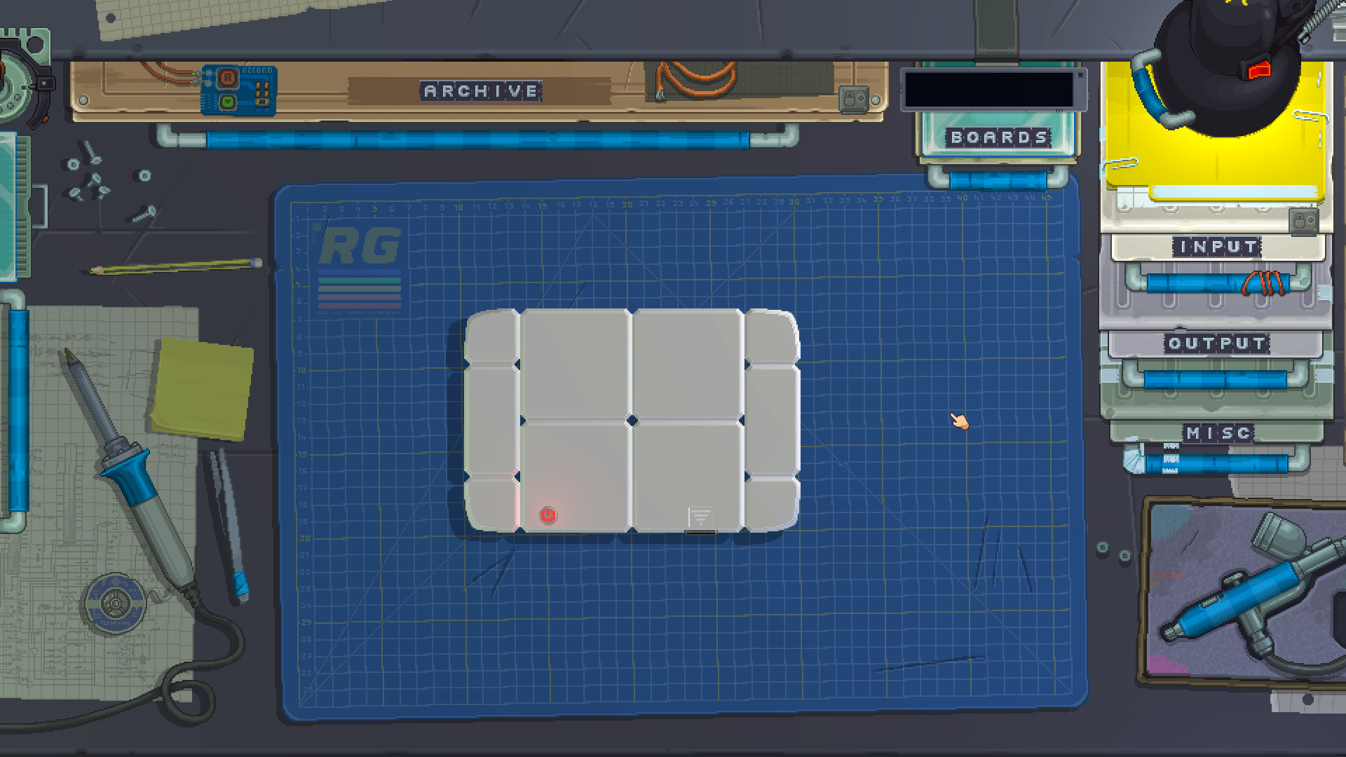
You don't have to follow this exact shape, as long as you have enough space in your gadget for all the components. Once they're all snapped together, you can use the soldering iron to join them.
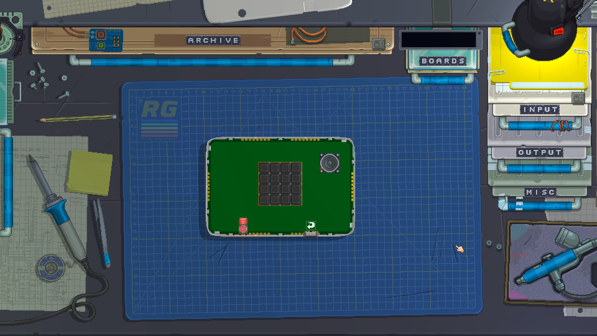
Now, click the little indentation in your gadget's front to open it. From the module drawers, place a Keypad and a Speaker on the front of your board.
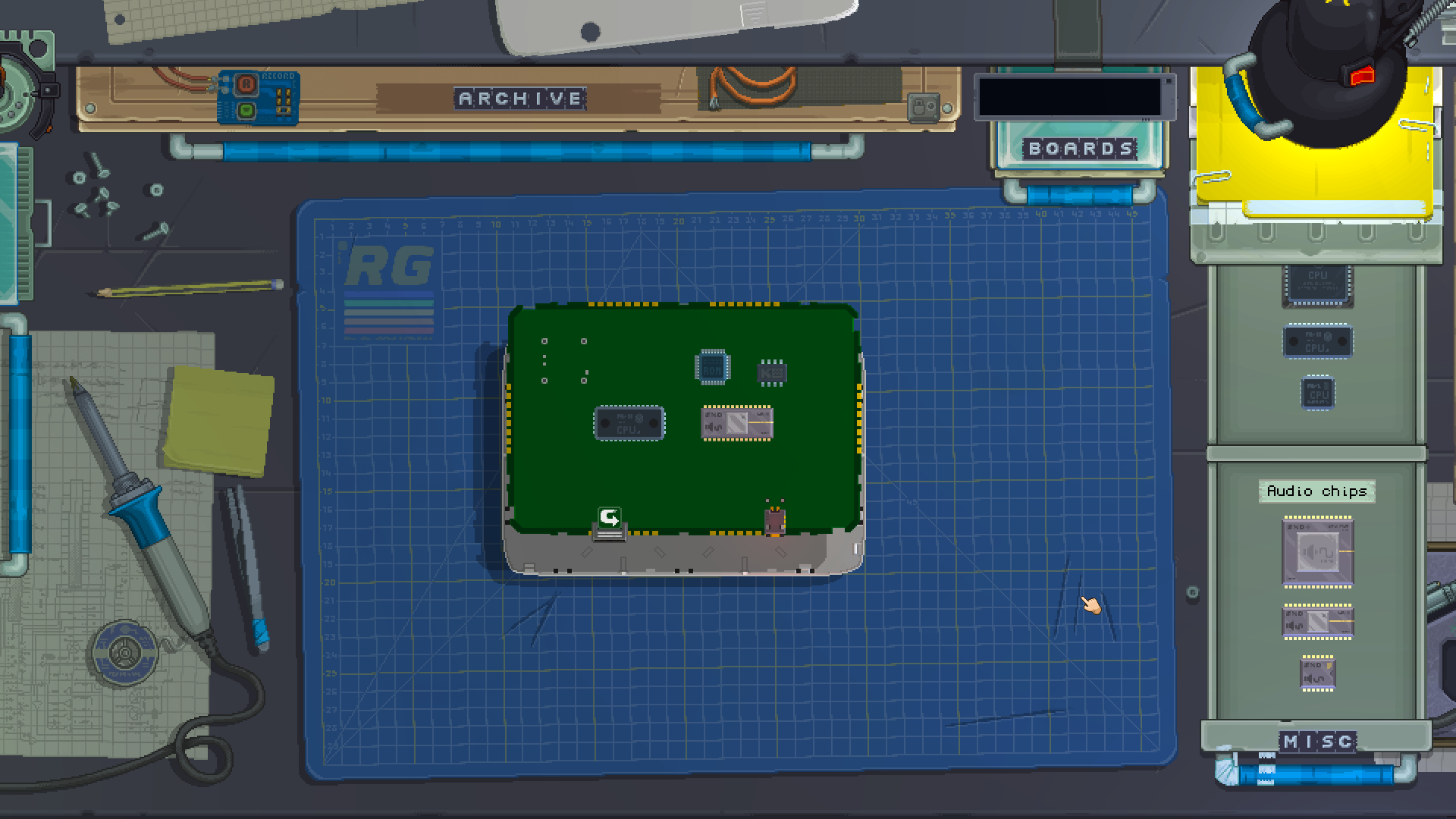
Once you've done that, click on the arrow where the indentation was on your board to flip it. On the back of the board, place a ROM, a CPU, a KeyboardChip and an AudioChip. Make sure the AudioChip is at least the medium size.
Setting up the modules
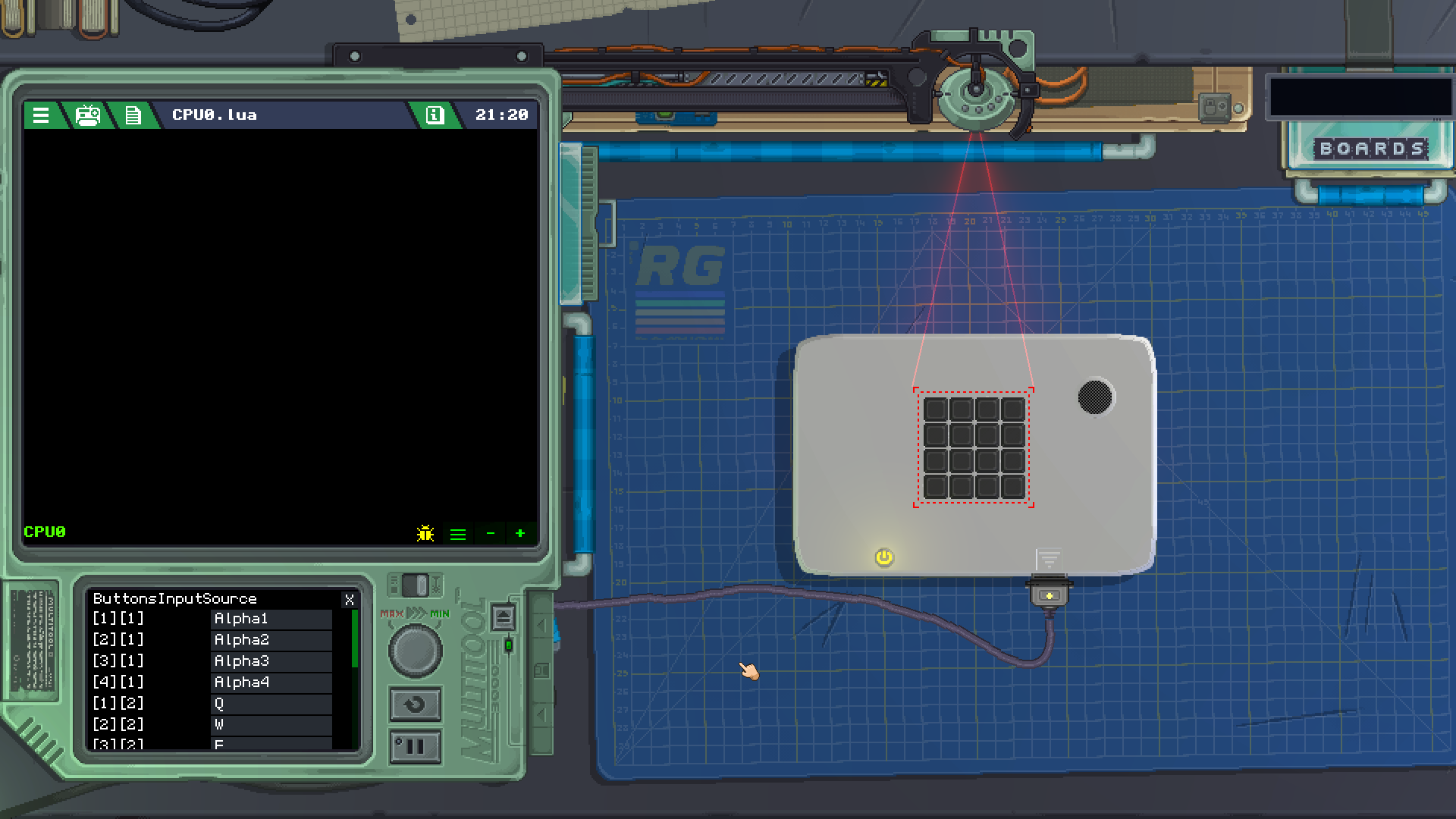
Now that you have all the modules in your gadget, click the shell of your gadget at the top of your screen to close it again. Open the Multitool and click the Keypad on your gadget. At the bottom of the Multitool you should see the module's properties.
In those properties, you can set the ButtonsInputSource of your Keypad, meaning we can give an external input to each one of its buttons. For this example, we are going to set each entry for the following KeyboardChip inputs by clicking on the bottom screen:
[1][1] | Alpha1 |
[2][1] | Alpha2 |
[3][1] | Alpha3 |
[4][1] | Alpha4 |
[1][2] | Q |
[2][2] | W |
[3][2] | E |
[4][2] | R |
[1][3] | A |
[2][3] | S |
[3][3] | D |
[4][3] | F |
[1][4] | Z |
[2][4] | X |
[3][4] | C |
[4][4] | V |
Now that those are set, you can try them out by clicking the PowerButton to power on your gadget and pressing the corresponding keys on your computer's keyboard. You should notice that each one of the keys on the left hand side of your keyboard correspond to the same positions on the Keypad.
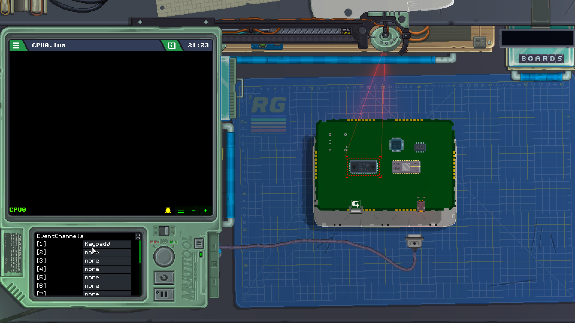
Turn off your gadget, open it back up and flip the board over. With the Multitool still open, click the CPU to set its EventChannels. You want the first EventChannel to point to your Keypad module. Since the Keypad has its inputs also tied to KeyboardChip keys, this event can be triggered both with your keyboard and by clicking the buttons of your gadget's Keypad.
Writing our code
You're now ready to add some code to your gadget! Open the Code Editor by double-clicking the CPU0.lua file in your Asset List. The code is the part of the puzzle that will take inputs from the Keypad buttons, load corresponding samples, then play them through the speaker.
Since we'll be starting from scratch, you can erase the initial boilerplate provided to us to start with an empty code file.
First, we need a table to tell which sample we want to play at each button of the Keypad:
local sampleNames = {
	{"","","",""},
	{"","","",""},
	{"","","",""},
	{"","","",""}
}
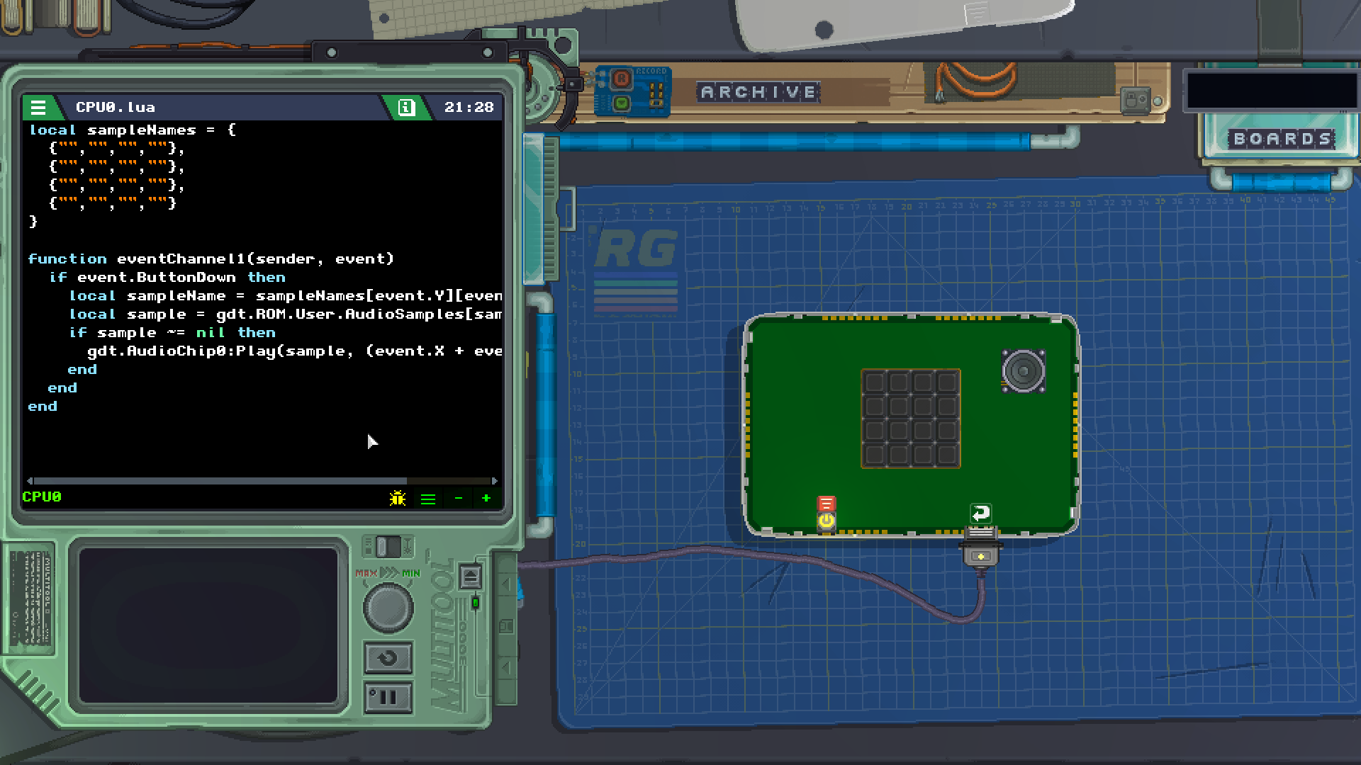
This will make a two-dimensional table with the same size as the Keypad, 4 columns and 4 rows. Right now all our sample names are empty, but we'll change that soon. Then, we'll make a handler for EventChannel number 1, which will handle events incoming from the Keypad.
function eventChannel1(sender, event)

	if event.ButtonDown then -- was the event caused by a button being pressed?

		local sampleName = sampleNames[event.Y][event.X] -- get the name of the sample from our table
		local sample = gdt.ROM.User.AudioSamples[sampleName] -- load that sample from our assets

		if sample ~= nil then -- is the sample we tried to load anything but nil?
			gdt.AudioChip0:Play(sample, (event.X + event.Y * 4)) -- play the sample we loaded
		end

	end

end
In this handler, we are first checking if the event was caused by a button being pressed. The code inside that condition will only run if it's true.
Next, we look into the table we prepared earlier to find which sample name we're supposed to play for this button. We use the X and Y values of the event for that, since they correspond to the column and row of the button that was pressed.
Once we have the name of the sample, we can use the ROM module to load the actual sample.
Next, another condition checks if the sample we tried to load actually exists. If it doesn't, the ROM will return nil, so our condition asks for a value different from that with the ~= logic operator.
After all that, we can ask the AudioChip to play the sample we loaded. Notice the bit of math in the place of a channel: (event.X + event.Y * 4). This will calculate a channel number depending on the column and row of the button pressed, making sure that no two buttons try to use the same audio channel. For that to work, we need to use an AudioChip that supports at least 16 channels.
Adding our assets
The last step we need to do is import some AudioSamples into our gadget so that our sound board has some sounds to play. You can choose any name for your samples when importing them into your gadget, just make sure to note the exact names you give them, including case sensitivity.
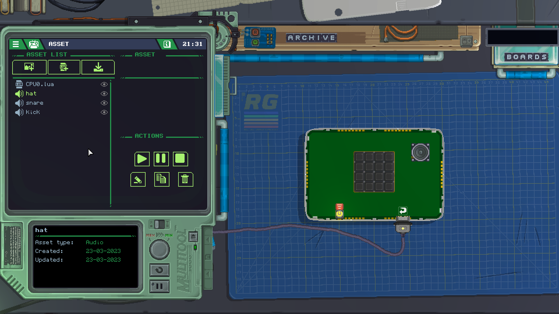
Once you've added those assets, go back to your gadget's CPU code to map them to the Keypad buttons using our table. Note how the table is structured in a way that the position of the sample names in it matches the position of the Keypad buttons. For this example, we used three samples like so:
local sampleNames = {
	{"kick","hat","",""},
	{"snare","","",""},
	{"","","",""},
	{"","","",""}
}

With everything in place, you should be able to turn on your gadget and press those keys to make some noise. Huzzah!
Finishing touches
Once your gadget is complete, you can decorate it however you want, paint it with the Airbrush however you like, and even add stickers to it.
Try adding some LEDs to make your gadget really shine. If you make something really cool, we'd love to see it in our Discord server!
Collect The Dot
This guide will show you how to move two single dots around a LED matrix, with some simple logic to increase a counter whenever the "player" dot reaches a "target" dot.
Building the gadget
Since we already covered in greater detail how to build a gadget in the previous example, we'll go over this part more succinctly. You'll need a LED matrix, a 2-digit segment display for our counter, and a D-Pad in the front of your gadget. For functionality, you'll need a KeyboardChip and a CPU somewhere in your gadget.
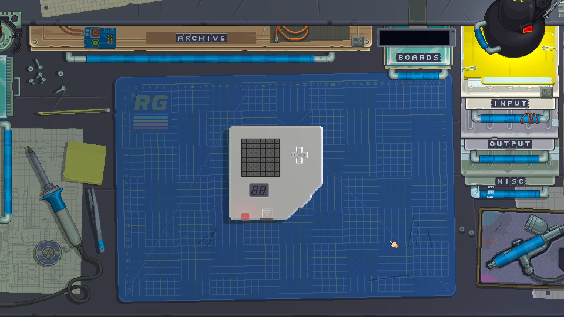
The segment display will be easier to read if you paint it a darker color with the Airbrush.
Setting up the modules
Like we've done with the Sound Board before, we're going to set some InputSources for our D-Pad control in the Multitool. Since the D-Pad expects axes, not individual buttons, we need to tell it which keys of the KeyboardChip will control each axis.
Once you click to set InputSourceX and pick from KeyboardChip0, the input will look for an axis. Since the KeyboardChip does not have an axis (an analog input like a game pad has), your only option will be a Buttons axis, that is, a virtual axis that will be controlled by 2 keys instead of an actual analog input.
- For InputSourceX, the horizontal axis, set Negative to LeftArrow and Positive to RightArrow
- For InputSourceY, the vertical axis, set Negative to DownArrow and Positive to UpArrow
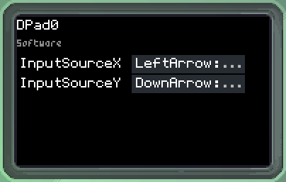
At this point you can turn on the gadget to see that your keyboard's arrow keys will move the D-Pad. After you've done that, set the CPU's EventChannel 1 to DPad0, this will make it so any movement on the D-Pad will trigger an event.
Writing our code
Since we'll be starting from scratch, you can erase the initial boilerplate provided to us to start with an empty code file.
First, let's make some shorthands to make our life easier when referencing each one of our gadget's modules:
local pad:DPad = gdt.DPad0
local matrix:LedMatrix = gdt.LedMatrix0
local counter:SegmentDisplay = gdt.SegmentDisplay0
This means we can refer to our D-Pad by just pad, the LED matrix by just matrix and our segment display by just counter in the rest of our code. We are also setting each respective type after each variable's name with a :, so the code editor will know how to give us auto-complete suggestions.
Now, let's create some variables to store the information we need for our purposes:
local playerX = 1
local playerY = 1
local playerColor = color.yellow
local goalX = 0
local goalY = 0
local goalColor = color.red
local countValue = 0
playerX and playerY will store the player's starting position. You can change these, keeping in mind that the LED matrix has 8 columns and 8 rows, starting from 1. playerColor is the color the player's dot will light up in the matrix, which you can also change.
goalX and goalY will store the goal's position, and goalColor its color. We don't need to set this position right now since we'll make a function to do that for us.
countValue will be the number of times the player has reached the goal, to be displayed in the segment display.
With those values in mind, let's write a couple functions that will use them. The first is a function to randomize the goal's position:
function randomizeGoal()
	-- this code will repeat until we quit
	while true do
		-- place the goal in a random spot
		goalX = math.random(1, 8)
		goalY = math.random(1, 8)
		-- only quit if the goal is not where the player is
		if goalX ~= playerX or goalY ~= playerY then
			return
		end
	end
end
Every time this function is called, it will change goalX and goalY to a different position. We start with a forever while loop, so that the code only exits when it has reached a specific condition we want.
In that loop, we are using math.random to generate an integer number between 1 and 8, to fit inside the LED matrix. We generate one such random number for the horizontal and the vertical positions of the goal respectively.
Next, we check if the goal's position is different (~=) from the player's position. Since we don't want the goal to be generated where the player is standing, we only quit this function (with return) if that is the case. Otherwise, the function will not quit, and the loop will start over again, generating new numbers until the condition is met.
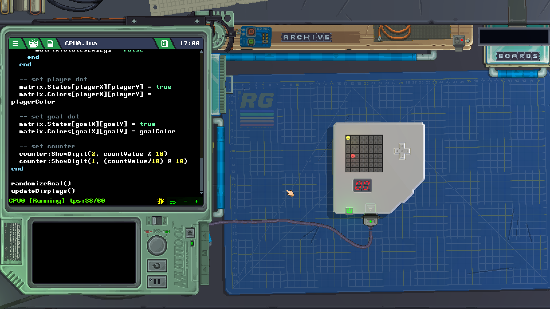
Now, we'll write a function to use the values we have to update our matrix and segment display:
function updateDisplays()
	-- clear all the matrix
	for x = 1, 8 do
		for y = 1,8 do
			matrix.States[x][y] = false
		end
	end

	-- set player dot
	matrix.States[playerX][playerY] = true
	matrix.Colors[playerX][playerY] = playerColor

	-- set goal dot
	matrix.States[goalX][goalY] = true
	matrix.Colors[goalX][goalY] = goalColor

	-- set counter
	counter:ShowDigit(2, countValue % 10)
	counter:ShowDigit(1, (countValue/10) % 10)
end
First, we are using a different type of loop, the for loop to run through the entire matrix and clear it. The two nested for functions will run each time with the values x and y iterating from 1 to 8. The nesting means that the inner loop will run 8 times for each of run the outer loop. Since both loops run 8 times, this means that the inner code will run 64 times, each single time with all permutations of x and y increasing from 1 to 8. The code inside the loop is using those values to set all of the LEDs in the matrix off, therefore we are clearing the entire matrix regardless of its current state.
Next, now that the matrix is cleared, we use playerX and playerY to set that particular LED in the matrix on, and then for it to be the player's color. Notice how in a LED matrix, we need to tell what column and row we want to set a State and a Color of.
The next part does the same thing, but for the goal dot.
Lastly, we make the counter segment display show our countValue using the ShowDigit method. We need to set each digit of the segment display individually, so we do that with some math. The second digit of the display shows the lower digit of our number, using modulo (%) to get the value's remainder from a division by 10. The first digit of the display shows the next higher digit, so we need to divide by 10 first, then take the same remainder from that number.
Once you have those two functions, call them at the end of your code so that they run once when your gadget is powered on:
randomizeGoal()
updateDisplays()
At this point you should be able to turn your gadget on and watch the red goal dot appear in a different position each time you power on your gadget. The segment display should read "00".
Now we'll write a handler for the D-Pad's events to move our player.
function eventChannel1(sender, event)
	-- i only want to run if the dpad changed to pressed, not released
	if event.X ~= 0 or event.Y ~= 0 then
		-- move horizontally
		if event.X < 0 and playerX > 1 then
			playerX -= 1
		elseif event.X > 0 and playerX < 8 then
			playerX += 1
		end

		-- move vertically
		if event.Y > 0 and playerY > 1 then
			playerY -= 1
		elseif event.Y < 0 and playerY < 8 then
			playerY += 1
		end

		-- if player overlaps goal, count up
		if playerX == goalX and playerY == goalY then
			countValue += 1
			randomizeGoal()
		end

		updateDisplays()
	end
end
We start by checking if the D-Pad was pressed, not released. Since when the D-Pad is released, both X and Y axes will read 0, we are checking if either one of them are different from 0.
To move the player horizontally, we check if the X axis is negative, and if the player is to the right of the leftmost edge (1). If both conditions pass, we decrease the player's X value to move it left. We also check if the X axis is positive and if the player is to the left of the rightmost edge (8). If those conditions pass instead, we move the player to the right.
The next part does the same for the vertical axis, however you must note that the D-Pad's Y axis is positive when pressed up and negative when pressed down, so those conditions are "reversed" when compared to the horizontal movement.
One last condition checks if the players X and Y positions match the goal's X and Y positions. This means that the player is overlapping the goal, and therefore has reached it. If that is true, then we increase the countValue and tell our program to randomize the goal again.
Finally, we call for the displays to be updated again. This means that each time we press a direction in the D-Pad we'll be able to see the LED matrix change.
You should be able to turn on your gadget, move your yellow player dot around and collect red dots to increase the number in the counter display.
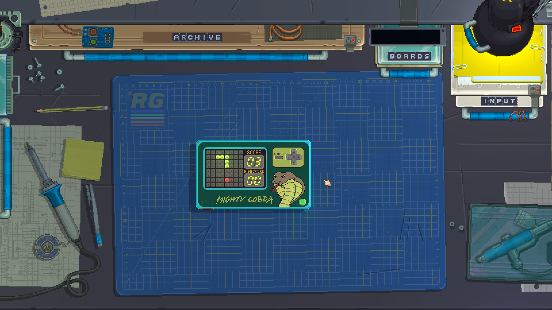
Conclusion
Now that you know how to take D-Pad inputs and set LEDs in a matrix, you should have enough knowledge to see how the Mighty Cobra game works! If you can't find this game in your Archive drawer, check the Tutorial button in the main menu for the built-in gadgets to print a copy.
Moving Mike
This example will show you how to make a D-Pad control the position of a sprite being drawn on a Screen with a VideoChip.
Building the gadget
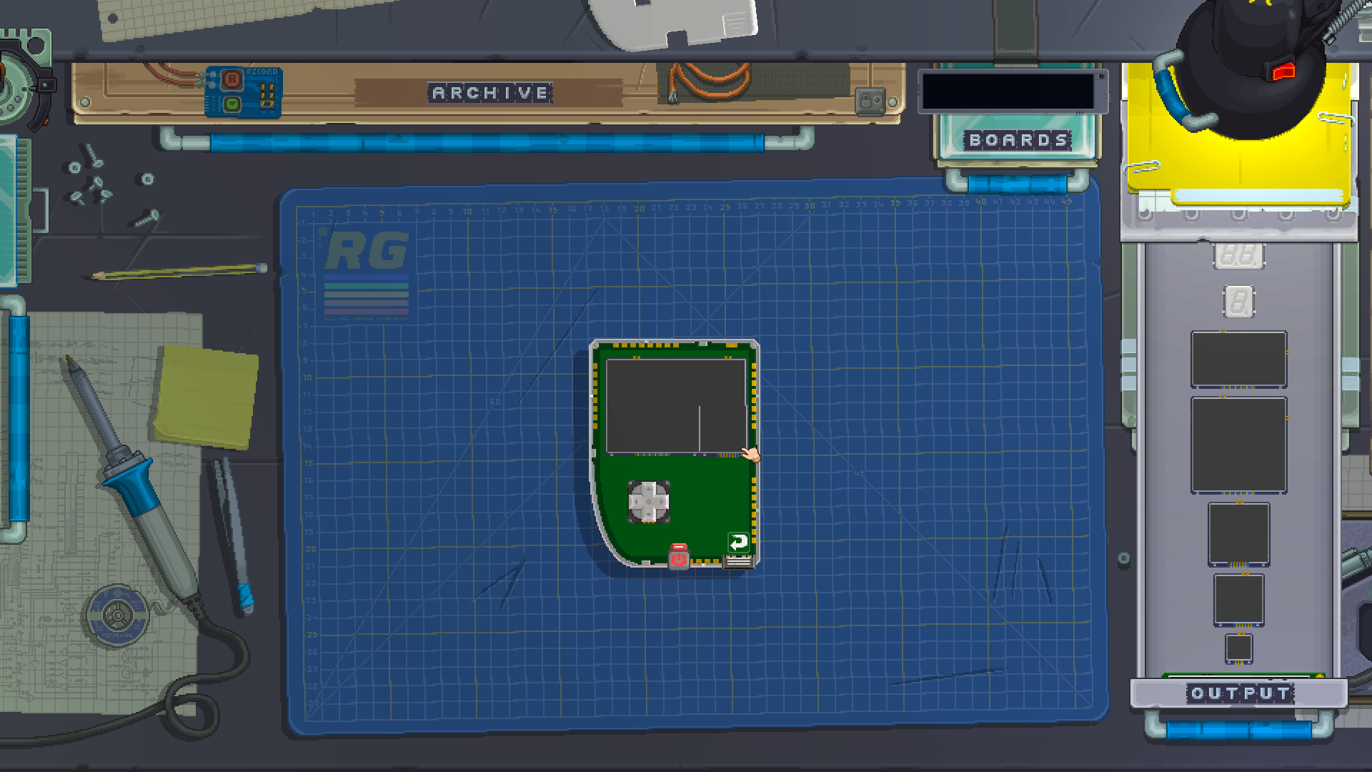
We are going to place screens and a D-Pad on the front of the gadget. For this example, we're using one large 64x64 screen to the left, joined with two 32x32 screens to make it wider.
Note that with precise positioning you can slightly overlap the edges of several screens together to form a bigger screen. If done correctly, you will see one big screen without the edges in between. The example below shows the smaller screen at the top right correctly positioned, and the bottom right one needing adjustment to the left to join properly. You can hold the left shift key to zoom in on your desk for higher precision.
Once you have those modules ready, go ahead and add a CPU, a KeyboardChip, a VideoChip and a ROM to your gadget as well.
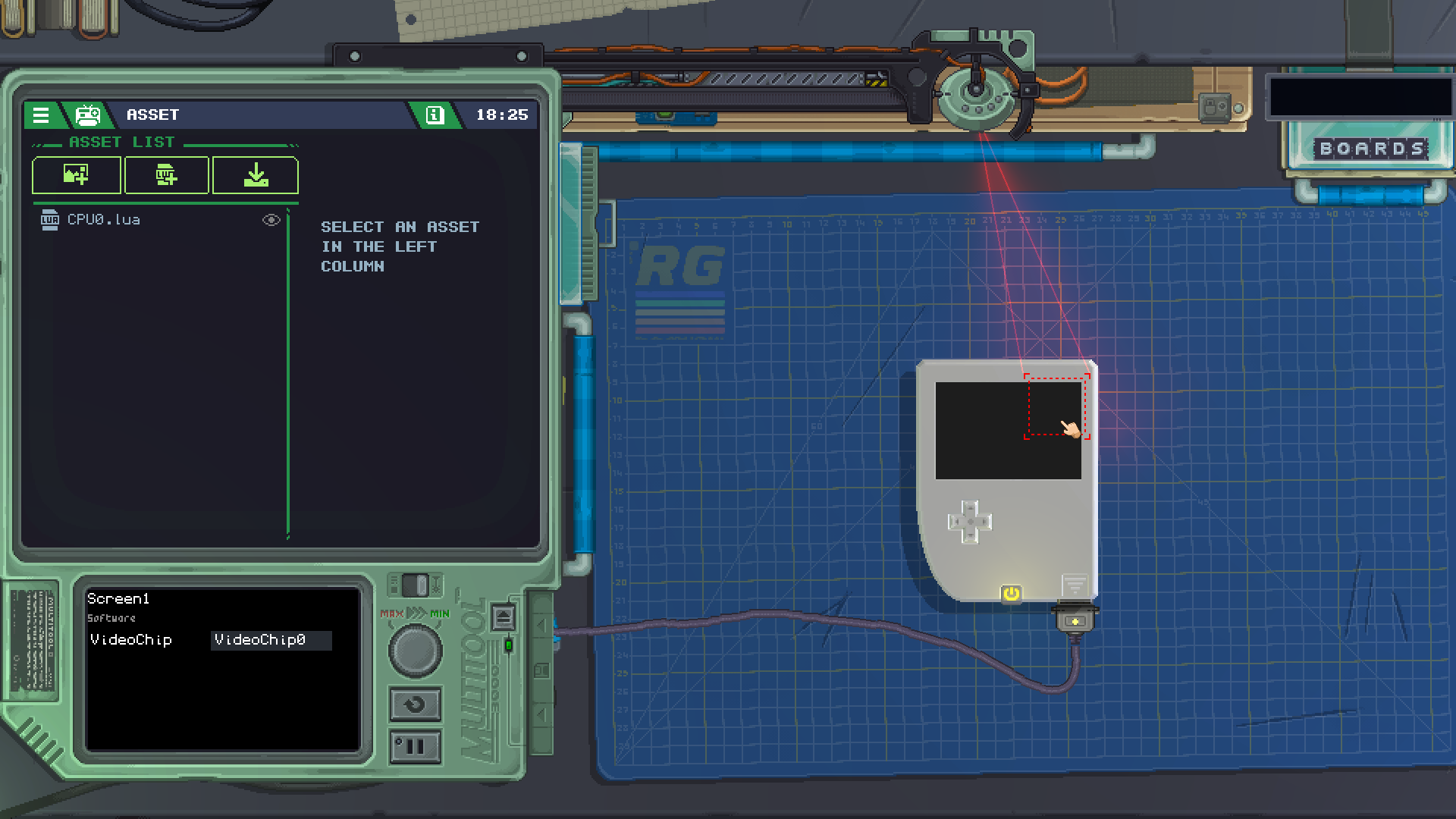
Setting up the modules
Despite being visually joined together, each screen still needs to be connected to a VideoChip. Since we want all of our screens to be part of the same display, we need to connect each one of them to the same VideoChip with the Multitool.
Once you have those done, you should set up the D-Pad to use KeyboardChip InputSources and the CPU to take events from the D-Pad in channel one, exactly the same way we've done previously in the Collect the Dot example.
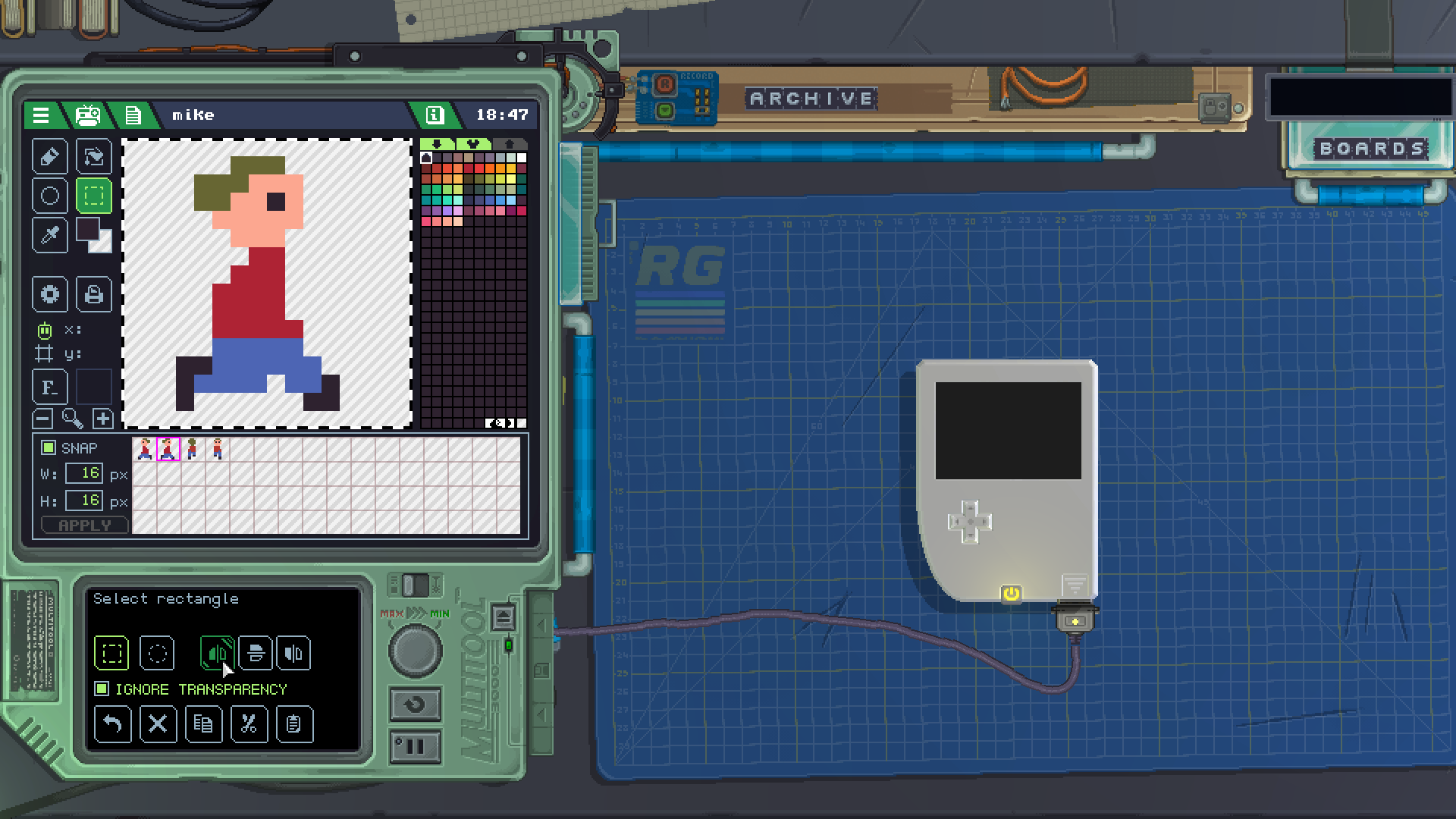
Making our assets
At the Asset List, we can click the first button to create a new SpriteSheet with the built-in Sprite Editor. For this example we'll be naming the asset mike exactly.
By default the editor will be set up to draw 16x16 sprites, we can use that as it is. Draw 4 sprites for our main character Mike, facing left, right, up and down, respectively. Remember you can use the selection tool to copy and flip sprites to make your job easier.
Writing our code
The code part of this gadget will be very similar to the one in the previous example, Collect the Dot. First, our module shorthands:
local pad:DPad = gdt.DPad0
local video:VideoChip = gdt.VideoChip0
local mike:SpriteSheet = gdt.ROM.User.SpriteSheets["mike"]
Here we are loading the mike SpriteSheet into a variable called mike so we can easily use it later.
Then, we'll store some values for the player:
local playerX = 0
local playerY = 0
local direction = 0
local stepSize = 5
The playerX and playerY variables work the same as before, but since the VideoChip buffer starts at 0, we can use those values instead of 1.
The direction value will remember which way we want Mike to face, that is, which sprite in his SpriteSheet we need to display.
The stepSize value will be used as how many pixels we want our sprite to move each time we press a direction.
The next part of the code will update our display:
function updateDisplays()
	-- clear the screen with white
	video:Clear(color.white)

	-- display mike's sprite
	video:DrawSprite(vec2(playerX,playerY), mike, direction, 0, color.white, color.clear)
end
First thing when calling the display update, we are clearing the video display so we don't keep whatever was on it previously. We are clearing with color.white which means the entire screen will be filled with that color.
The DrawSprite method might look daunting, but it can be easily broken down into each of its arguments:
- First, we are telling it we want the sprite to be put into the
vec2coordinate ofplayerXandplayerY - Then, we are telling that the SpriteSheet we want to use is
mike - The next two ones,
directionand0tell which sprite within the SpriteSheet we want to display. These two values are the horizontal and vertical position in the grid we can see while in the Sprite Editor. In the starting values, this means to pick the very first sprite, which is Mike facing left. - The next value is which color to tint the sprite with. We don't want to affect its color, so we use
color.white. - Last, this value is which color to replace the sprite's transparency with. We want it to be transparent, so we use
color.clear.
Once you have that function in, add a call at the end of your script so that it runs once when your gadget is turned on:
updateDisplays()
At this point, you can turn on your gadget and see the display shows Mike on the top left corner, facing left.
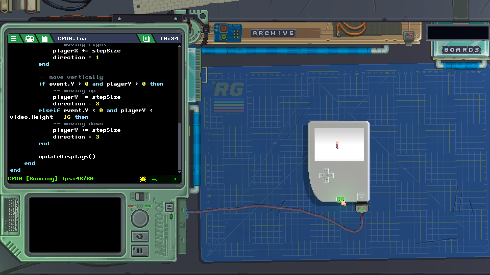
Now, we'll be controlling the movement of the sprite with a D-Pad event handler very similar to the one used in Collect the Dot:
function eventChannel1(sender, event)
	-- i only want to run if the dpad changed to pressed, not released
	if event.X ~= 0 or event.Y ~= 0 then
		if event.X < 0 and playerX > 0 then
			-- moving left
			playerX -= stepSize
			direction = 0
		elseif event.X > 0 and playerX < video.Width - 16 then
			-- moving right
			playerX += stepSize
			direction = 1
		end

		-- move vertically
		if event.Y > 0 and playerY > 0 then
			-- moving up
			playerY -= stepSize
			direction = 2
		elseif event.Y < 0 and playerY < video.Height - 16 then
			-- moving down
			playerY += stepSize
			direction = 3
		end

		updateDisplays()
	end
end
The main differences in this code is that now for up and left movement we are checking if the player is above coordinate 0 in either way instead of 1, and for the other edges moving right and down we are checking against the Width and Height properties of the VideoChip. Those properties will return the size of the screen taking into account all of the screens connected to the same VideoChip, so we don't need to keep track of how big our screen is by hand. Also, we are subtracting 16 from those values since that's the width and the height of our sprite, otherwise the sprite would be allowed to travel beyond the bottom right edge of the screen.
On each movement, we are increasing or decreasing the player's coordinates by a value of stepSize. This way if we decide to change by how much the sprite should move at each press of the button, we can change a single variable instead of having to change it each time it appears in our code.
And lastly, when moving our character, we are changing the direction value to correspond to each different sprite in our SpriteSheet, so that when the screen gets updated Mike will be facing the direction we are moving him in.
Now you know the basics of how to move a sprite on the screen!
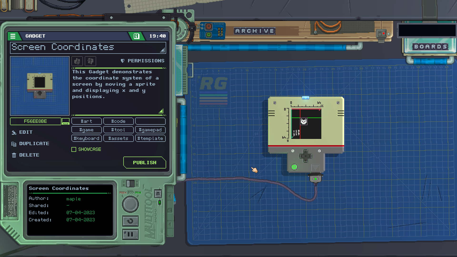
Conclusion
A very similar built-in gadget you can look at is Screen Coordinates, which you can find in the Tutorial section in the main menu of the game. The method used to move the sprite is different, reading the D-Pad inside the update() function instead of events, so you might want to read the code and see how it works!
Libs
By clicking on this button in the assets app you can import some libraries
The assets of the imported libraries will be added to the gadget and can be used by code with the require() method.
RG Game library
Overview
RetroLib is a Lua library designed to facilitate the development of 2D games and applications in Retro Gadget. It provides functionality for graphics rendering, collision detection, easing animations, and various utility functions.
You can find a sample Gadget that uses the library in the tutorial section of the game.
Graphics
lib.CreateSprite( spritesheet SpriteSheet, spriteX, spriteY, position vec2, scale vec2, animationSpeed number, renderOrder number ) table
This function creates and return a sprite instance with the specified parameters and adds it to the rendering queue.
Sprites can be dynamically positioned, scaled, and animated.
Sprite variables:
spritesheetThe spritesheet containing the sprite image.spriteX,spriteYThe coordinates of the sprite image within the spritesheet.positionThe position of the sprite in 2D space.rotationThe angular rotation of the sprite in 2D space.scaleThe scaling factor of the sprite.colorThe base color of the sprite. By default is set to color.whitebgColorThe base color of the background of the sprite. By default is set to color.clearflipXStore the flip status of the sprite on the X axisflipYStore the flip status of the sprite on the Y axisframeCurrent frame of the current sprite animationanimationsTable of sprites coordinates animationanimationSpeedThe speed of animation playbackcurrentAnimationthe index of the currently playing animationcollidertable of the colliders added to the spriteactivedetermine if the sprite is rendered or not *renderOrderThe order in which the sprite is rendered relative to other sprites.
Sprite methods:
sprite:FlipSpriteX( flip boolean )
Flips the sprite horizontally if flip value is true. Flip value is stored in the sprite.
sprite:FlipSpriteY( flip boolean )
Flips the sprite vertically if flip value is true. Flip value is stored in the sprite.
sprite:RotateSprite( angle )
Rotates the sprite by the specified angle (in radians).
sprite:ScaleSprite( scale vec2 )
Scales the sprite by the specified scale vector.
sprite:MoveX( xValue )
Moves the sprite horizontally by the specified xValue.
sprite:MoveY( yValue )
Moves the sprite vertically by the specified yValue.
sprite:Move( position vec2 )
Moves the sprite to the specified position.
sprite:SetRenderOrder( value number )
Sets the rendering order of the sprite.
Starts the animation of the sprite.
Stops the animation of the sprite.
sprite:CreateAnimation( animations )
Creates an animation for the sprite.
sprite:SetAnimation( animation number )
Sets the current animation of the sprite.
Draws the animated sprite.
Draws the sprite without animation.
Collisions
CircleCollider:new( position vec2, radius number, tag string ) table
Creates and return a circle collider with the specified parameters.
CircleCollider variabiles:tagcan be used to check the colliderpositionthe position of the colliderradiusthe radius of the circle collidertypethe type of the collider
BoxCollider:new( position vec2, width number, height number, tag string ) table
Creates and return a box collider with the specified parameters.
BoxCollider variables:tagcan be used to check the colliderpositionthe position of the colliderwidththe width of the boxheightthe height of the boxcentrethe centre of the box based on its sizetypethe type of the collider
Easings
lib.EasingTypes = {
  Linear
  InQuad
  OutQuad
  InCubic
  OutCubic
  InQuart
  OutQuart
  InQuint
  OutQuint
  InSine
  OutSine
  InExpo
  OutExpo
  InCirc
  OutCirc
  InElastic
  OutElastic
  InBack
  OutBack
  InBounce
  OutBounce
}
The easings need four parameters:
- t = time
- b = begin
- c = change (ending - beginning)
- d = duration
lib.EasingManager:new( ) table
Creates and return a new easing manager.
Creates a new easing instance.
easing:EaseNumber( startValue, endValue, duration, easingType, onEaseValue, onEaseComplete )
Applies an easing function to interpolate between values.
Updates active easings.
Utils
lib.moveTableElement( table, fromIndex, toIndex )
Moves an element within a table.
lib.findIndex( table, element )
Finds the index of an element in a table.
Debug
Debugging RetroLib provides a debug mode that can be toggled on or off. When enabled, debug messages are printed to the console and colliders are drawn providing useful information for troubleshooting and monitoring the library's behaviour.
To enable debug mode, set lib.debugMode to true:
lib.debugMode = true
Modules
Input
Output
Misc
- AudioChip
- CPU
- Decoration
- FlashMemory
- GamepadChip
- KeyboardChip
- MagneticConnector
- PowerButton
- RealityChip
- ROM
- SecurityChip
- VideoChip
- Wifi
- Serial
AnalogStick
A little joystick-like input device for your gadget, which has smooth movement in all directions.
Similar to the D-Pad in functionality.
Properties
The position of the stick along the horizontal axis, ranging from -100 to 100.
The position of the stick along the vertical axis, ranging from -100 to 100.
The module associated with the stick's horizontal axis. See InputSource for more info.
The module associated with the stick's vertical axis. See InputSource for more info.
Events
StickValueChangeEvent : { X number, Y number, Type string }
Triggered when the stick is moved.
*XandYare the respective values of the stick
*Typeis"StickValueChangeEvent"
In the Multitool
You can set the InputSource properties from the Multitool while editing your gadget to set these values without using code.
DPad
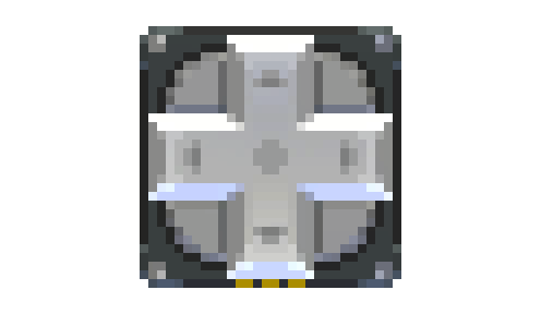
A digital directional input device for your gadget, which returns what directions are being pressed.
Similar to the Analog Stick in functionality.
Properties
The position of the pad along the horizontal axis, only returns -100 or 100 when pressed, 0 when not.
The position of the pad along the vertical axis, only returns -100 or 100 when pressed, 0 when not.
The module associated with the stick's horizontal axis. See InputSource for more info.
The module associated with the stick's vertical axis. See InputSource for more info.
Events
DPadValueChangeEvent : { X number, Y number, Type string }
Triggered when the D-Pad is pressed.
*XandYare the respective values of the pad
*Typeis"DPadValueChangeEvent"
In the Multitool
You can set the InputSource properties from the Multitool while editing your gadget to set these values without using code.
Examples
See the Collect the Dot cookbook example for an example on how to address individual LEDs in the matrix with D-Pad input.
Keypad
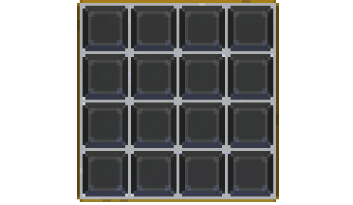
A grid of buttons that can be used in a group.
Properties
A Keypad works similarly to a grid of Buttons, its properties are all multi-dimensional tables that correspond to each button in the Keypad. The tables should be addressed with [column][row].
ButtonsState {{boolean}} read only
A multi-dimensional table mapping the state of each button to a boolean value.
Returnstrueif the corresponding button is currently pressed,falseotherwise.
ButtonsDown {{boolean}} read only
A multi-dimensional table mapping boolean flags which will be true only in the time tick the corresponding button changes its state to pressed.
ButtonsUp {{boolean}} read only
A multi-dimensional table mapping boolean flags which will be true only in the time tick the corresponding button changes its state to released.
ButtonsInputSource {{InputSource}}
A multi-dimensional table mapping InputSources to each of the buttons in the Keypad.
Events
KeypadButtonEvent : { X number, Y number, ButtonDown boolean, ButtonUp boolean, Type string }
Triggered when a button is pressed or released.
*Xis the column of the button that triggered the event.
*Yis the row of the button that triggered the event.
*ButtonDownistrueif the button was just pressed.
*ButtonUpistrueis the button was just released.
*Typeis"KeypadButtonEvent".
In the Multitool
You can select different symbols to be printed on each one of the buttons of the keypad in the bottom screen of your Multitool.
Examples
See the Sound Board cookbook example for an example on how to play samples with keypad input.
Knob
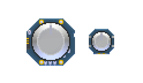
A circular component that rotates to set numerical values. In Default mode the value goes from -100 on the left to 100 on the right. When set to Infinite mode the rotation is unclamped and the value is the absolute angle in degrees.
Similar to the Slider in functionality.
Properties
The mode of the Knob:
In Default mode the value goes from -100 on the left to 100 on the right.
When set to Infinite mode the rotation is unclamped and the value is the absolute angle in degrees.
The value returned by the position of the knob.
In Default mode the value goes from -100 on the left to 100 on the right.
When set to Infinite mode the rotation is unclamped and the value is the absolute angle in degrees.
The rotation delta from the previous update.
Returns
trueif the user is moving the knob.
Events
KnobValueChangeEvent : { Value number, Type string }
Triggered when the knob is moved.
*Valueis the respective value given by the knob's position
*DeltaValueis the the rotation delta from the previous update
*Typeis"KnobValueChangeEvent"
Examples
A simple code using some math to map knob's value into the hue of a LED's color:
-- a function that maps "value"
-- from a scale of "src_from" to "src_to"
-- into a scale of "tgt_from" to "tgt_to"
function map(value, src_from, src_to, tgt_from, tgt_to)
	return ((value - src_from) / (src_to - src_from) * (tgt_to - tgt_from)) + tgt_from
end

-- turn LED on at startup
gdt.Led0.State = true

function update()
	-- map slider -100,100 to hue 0,360
	local hue = map(gdt.Knob0.Value, -100, 100, 0, 360)

	-- set LED color to hue
	gdt.Led0.Color = ColorHSV(hue, 100, 100)
end
LedButton
A button that can tell when it's pressed or released, and can glow with a LED embedded in it.
Properties
ButtonState boolean read only
Returns
trueif the button is currently pressed,falseotherwise.
ButtonDown boolean read only
A boolean flag which will be true only in the time tick the corresponding button changes its state to pressed.
A boolean flag which will be true only in the time tick the corresponding button changes its state to released.
An InputSource to be used to trigger the button state.
The lit/unlit state of the Led of this button.
The color of the Led of this button.
Events
LedButtonEvent : { ButtonDown boolean, ButtonUp boolean, Type string }
Triggered when the LedButton is pressed or released.
*ButtonDownistrueif the button was just pressed.
*ButtonUpistrueis the button was just released.
*Typeis"LedButtonEvent".
In the Multitool
You can select different symbols to be printed on some sizes of buttons in the bottom screen of your Multitool.
Examples
You can tie the state of the button and the state of the LED together to make a button light up while it's pressed:
function update()
	-- LED state always being set to Button state every tick
	gdt.LedButton0.LedState = gdt.LedButton0.ButtonState
end
See also the Intro Tutorial video in the official Retro Gadgets YouTube channel for an example to control LED strips with Buttons.
ScreenButton
A button that can display images on itself, meaning that it works like a Screen and a Button at the same time.
The resolution of the screen inside the button is 16x16.
Properties
ButtonState boolean read only
Returns
trueif the button is currently pressed,falseotherwise.
ButtonDown boolean read only
A boolean flag which will be true only in the time tick the corresponding button changes its state to pressed.
A boolean flag which will be true only in the time tick the corresponding button changes its state to released.
An InputSource to be used to trigger the button state.
The VideoChip the screen part of this button is bound to.
The offset of the screen's top-left position in the corresponding VideoChip's overall rendering buffer.
The width of the screen in pixels.
The height of the screen in pixels.
Events
ScreenButtonEvent : { ButtonDown boolean, ButtonUp boolean, Type string }
Triggered when the ScreenButton is pressed or released.
*ButtonDownistrueif the button was just pressed.
*ButtonUpistrueis the button was just released.
*Typeis"ScreenButtonEvent".
Slider
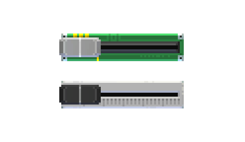
A linear component that slides from one end to the other to set numerical values.
Similar to the Knob in functionality.
Properties
The value returned by the position of the slider, ranging from 0 to 100.
Returns
trueif the user is moving the slider.
Events
SliderValueChangeEvent : { Value number, Type string }
Triggered when the slider is moved.
*Valueis the respective value given by the slider's position
*Typeis"SliderValueChangeEvent"
Examples
A simple code using some math to map the slider's value into the hue of a LED's color:
-- a function that maps "value"
-- from a scale of "src_from" to "src_to"
-- into a scale of "tgt_from" to "tgt_to"
function map(value, src_from, src_to, tgt_from, tgt_to)
	return ((value - src_from) / (src_to - src_from) * (tgt_to - tgt_from)) + tgt_from
end

-- turn LED on at startup
gdt.Led0.State = true

function update()
	-- map slider 0-100 to hue 0-360
	local hue = map(gdt.Slider0.Value, 0, 100, 0, 360)

	-- set LED color to hue
	gdt.Led0.Color = ColorHSV(hue, 100, 100)
end
Switch
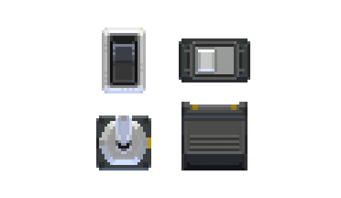
Works similar to a Button, but holds its state as flipped or not flipped instead of being a momentary push button.
Properties
The state of this switch.
An InputSource to be used to trigger the switch's state.
Events
SwitchStateChangeEvent : { State boolean, Type string }
Triggered when the Switch is flipped.
*Stateis the new state of this switch.
*Typeis"SwitchStateChangeEvent".
Webcam
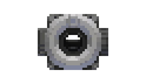
Properties
The VideoChip this camera is streaming contents to.
AccessDenied boolean read only
Will return
trueif Camera access is denied. See Permissions for more information.
Returns
trueif the Webcam is currently being used.
IsAvailable boolean read only
Returns
trueif the Webcam is available for being used.
Methods
GetRenderBuffer( ) RenderBuffer
Gets the camera RenderBuffer. The render buffer obtained can then be fed to the DrawRenderBuffer method of the VideoChip module.
Events
WebcamIsActiveEvent : { IsActive boolean, IsAvailable boolean, AccessDenied boolean, Type string }
Triggered when the Webcam's active state changes.
*IsActiveistrueif the Webcam is being used.
*IsAvailableistrueif the Webcam is available for use.
*AccessDeniedistrueif permissions are disabled for Webcams.
*Typeis"WebcamIsActiveEvent".
Examples
See the Camera Component Tutorial video in the official Retro Gadgets YouTube channel.
AnalogGauge
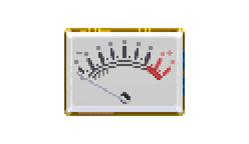
A physical device for visualizing a numerical value with a moving needle.
Properties
Setting this to a number between 0 and 100 will move the needle from left to right relative to that number.
Examples
Here's some code that sets an AnalogGauge to 100 if a LedButton is pressed down:
function update()
	-- if the button is pressed down
	if gdt.LedButton0.ButtonState then
		-- then the gauge gets set to 100
		gdt.Gauge0.Value = 100
	-- otherwise
	else
		-- the gauge will be set to 0
		gdt.Gauge0.Value = 0
	end
end
Note that even though the setting of the value is instantaneous, since the physical needle of the gauge can't move instantly, you can see it bounce between 0 and 100 in this example.
LcdDisplay
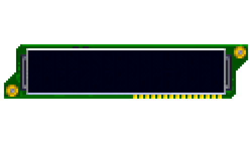
The LcdDisplay is an alphanumerical display consisting of 2 lines, 16 characters per line. It cannot display graphics and doesn't need a VideoChip to work.
Note: Unlike the other modules, the LcdDisplay does not follow its class' name for its objects, using Lcd instead, like so:
gdt.Lcd0
Properties
The text to be visualized on the LCD. To display text on the second line, your string must be formatted starting from the 17th character and beyond.
Background color for the LCD.
Foreground color for the LCD's text.
Examples
A small piece of code to change the LCD Display background color, displaying the hue value in text:
-- store a value for hue
local hue = 0

function update()
	-- put the hue value converted to text on display
	gdt.Lcd0.Text = "Hue: " .. tostring(hue)

	-- change display background color with hue
	gdt.Lcd0.BgColor = ColorHSV(hue, 100, 75)

	-- increase hue and wrap back to 0 once it reaches 360
	hue = (hue + 1) % 360
end
Led
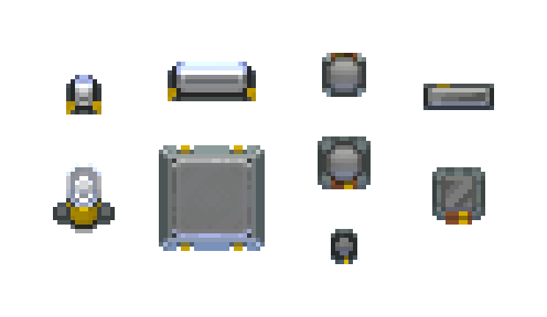
A small light that can change colors.
Properties
LED on/off state.
LED color.
Examples
A small piece of code for a color-changing LED:
-- turn the LED on once at startup
gdt.Led0.State = true

-- store a value for hue
local hue = 0

function update()
	-- set LED color with hue
	gdt.Led0.Color = ColorHSV(hue, 100, 100)

	-- increase hue and wrap back to 0 once it reaches 360
	hue = (hue + 1) % 360
end
LedMatrix
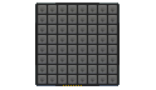
A two-dimensional cluster of LEDs that can be addressed individually.
Properties
A LedMatrix works similarly to a grid of LEDs, its properties are all multi-dimensional tables that correspond to each LED in the LedMatrix. The tables should be addressed with [column][row].
A multi-dimensional table that maps each of the LED's lit/unlit status.
A multi-dimensional table that maps each of the LED's colors.
Examples
See the Collect the Dot cookbook example for an example on how to address individual LEDs in the matrix with D-Pad input.
LedStrip
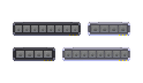
LedStrips are several LEDs joined together into one group.
Properties
A LedStrip works similarly to an array of LEDs, its properties are tables that correspond to each LED in the LedStrip. The tables should be addressed with [index].
A table that maps each of the LED's lit/unlit status.
A table that maps each of the LED's colors.
Examples
This example uses the CPU's Time to select a LED to turn on, such that a light moves on the strip each second. Since the lights will stay on until we tell them not to, the code also gets the previous light to turn off, otherwise all lights on the strip would come on and stay on forever.
function update()
	-- round down cpu time and then truncate to the number of leds in our strip
	local ledToTurnOff = math.floor(gdt.CPU0.Time) % #gdt.LedStrip0.States
	-- we do the same with the next number over to get the adjacent light
	local ledToTurnOn = math.floor(gdt.CPU0.Time+1) % #gdt.LedStrip0.States

	-- since the modulo truncation starts at 0 and the states table starts at 1, we need to add 1 to both numbers
	gdt.LedStrip0.States[ledToTurnOff+1] = false
	gdt.LedStrip0.States[ledToTurnOn+1] = true
end
See also the Intro Tutorial video in the official Retro Gadgets YouTube channel for an example to control LED strips with Buttons.
Screen
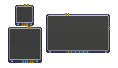
A screen is what displays the images you generate with a VideoChip.
Sizes
Screens come in five different sizes with the following resolutions each:
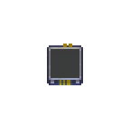 16x16
16x16
 32x32
32x32
 40x40
40x40
 64x36
64x36
 64x64
64x64
By carefully positioning two or more screens next to each other, you're able to join them together to make screens of different sizes and shapes. Remember you still need to individually connect each separate screen to your VideoChip in order to display images on them.
Properties
The VideoChip this screen is bound to.
The offset of the screen's top-left position in the corresponding VideoChip's overall rendering buffer.
The width of the screen in pixels.
The height of the screen in pixels.
SegmentDisplay
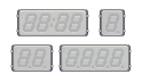
A collection of different seven-segment displays for showing numbers.
Segments
Each digit of a SegmentDisplay has its segments enumerated as such:
 1
1
 2
2
 3
3
 4
4
 5
5
 6
6
 7
7
 8
8
Each digit of a multi-digit display has all these segments, except for the display with two dots in the middle. In the case of that display, the two dots are instead enumerated as their own "digit" in which each segment is each dot, making the total of "digits" for it 5. Additionally, the 8th segment (the dot) is absent.
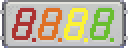 4 digits
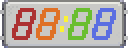 5 "digits"
Properties
The displays are enumerated in tables of tables. The outer table is each display digit, the inner table is each segment in that digit. Therefore the tables must be accessed by [digit][segment].
A table that maps the lit/unlit state of each of the segments in the display.
A table that maps the color of each of the segments in the display.
Methods
ShowDigit( groupIndex number, digit number )
A helper function to show a numerical digit in a whole display.
groupIndexis the digit that you want the number to show on,digitis the number you want to show.
SetDigitColor( groupIndex number, color color )
A helper function to set the color of a whole numerical digit at once.
groupIndexis the digit that you want to change the color of,coloris the color you want to set it to.
Examples
Here's how to display the CPU time (measured in seconds) on a 4-digit SegmentDisplay:
-- shorthand display module to "disp"
local disp = gdt.SegmentDisplay0

function update()
	-- store the CPU time rounded down
	local time = math.floor(gdt.CPU0.Time)

	-- each digit gets remainder of division by 10
	-- each next digit gets divided by 10 to get next decimal place
	disp:ShowDigit(4, time % 10)
	disp:ShowDigit(3, (time/10) % 10)
	disp:ShowDigit(2, (time/100) % 10)
	disp:ShowDigit(1, (time/1000) % 10)
end
The Collect the Dot cookbook example also makes use of a SegmentDisplay to show an increasing counter.
Speaker
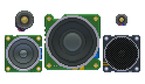
The Speaker outputs audio played with an AudioChip.
Sizes
Currently the different speaker sizes are purely cosmetic for your gadget's look, they all function the same.
Properties
Sets whether the speaker is enabled.
AudioChip
The AudioChip can be used together with a Speaker to make your gadgets produce sounds through the usage of AudioSamples.
Sizes
The different sizes of AudioChips determine how many concurrent channels each of them supports:
 The small AudioChip supports 4 channels.
 The medium AudioChip supports 16 channels.
 The large AudioChip supports 32 channels.
Properties
ChannelsCount number read only
Number of available channels for this AudioChip. Each channel can independently play an audio sample.
The global AudioChip volume.
Methods
GetSpectrumData( channel number, samplesCount number ) {number}
Returns the audio spectrum values of a
channelas a table of number values, each one expressing the value of a different frequency.samplesCountmust be a power of 2 (ie 128/256/512 etc) Min = 64 Max = 8192.
GetDspTime( ) number
Returns the current internal AudioChip's DSP time. It is meant to be used in combination with the PlayScheduled method. The returned number is expressed in seconds.
Play( audioSample AudioSample, channel number )
Immediately plays an AudioSample on a specific
channel.
PlayScheduled( audioSample AudioSample, channel number, dspTime number )
Schedule the play of and AudioSample at a specific DSP time, expressed in seconds, on the specific
channel.
PlayLoop( audioSample AudioSample, channel number )
Immediately plays an AudioSample on a specific
channel, looping it.
PlayLoopScheduled( audioSample AudioSample, channel number, dspTime number )
Schedule the play of and AudioSample at a specific DSP time, expressed in seconds, on the specific
channel, looping it.
Stops any audio playing on a specific
channel
Pause the audio on a specific
channel
Resumes the audio on a specific
channel
IsPlaying( channel number ) boolean
Returns true if a
channelis currently playing audio
IsPaused( channel number ) boolean
Returns true if a
channelis currently paused.
GetPlayTime( channel number ) number
Returns the current play time of a
channel, expressed in seconds.
SeekPlayTime( time number, channel number )
Sets the current position of the play head, for the specific
channel, expressed in seconds.
SetChannelVolume( volume number, channel number )
Sets the current
volumefor achannel, 0-100 range.
GetChannelVolume( channel number ) number
Gets the current volume for a
channel, 0-100 range.
SetChannelPitch( pitch number, channel number )
Sets the
pitchfor achannel. Acts as a multiplier. A value of 1 means the defaultpitchfor a sample, a value of 2 plays the sample one octave higher.
GetChannelPitch( channel number ) number
Gets the current pitch of a
channel.
Events
AudioChipChannelEvent : { Channel number, Type string }
Event sent when a channel has finished playing.
*Channelis the index of the audio channel.
*Typeis"AudioChipChannelEvent".
Examples
See the Sound Board cookbook example for an example on how to play samples with keypad input.
See also the Audio Tutorial video in the official Retro Gadgets YouTube channel.
CPU
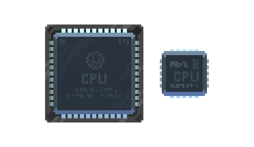
The CPU is what runs the Code assets in your gadget to control all your gadget's modules.
Sizes
The different CPU sizes support different amounts of EventChannels at once.
 The small CPU can have up to 4 EventChannels.
 The medium CPU can have up to 16 EventChannels.
 The large CPU can have up to 64 EventChannels.
Aside from that, the different CPU sizes do not operate differently.
Properties
The code asset uploaded to the CPU.
The time since the gadget is turned on, expressed in seconds.
The time elapsed since the last tick, expressed in seconds.
A table which is used to connect each Event Channel with a module in your gadget that can trigger that channel with its events.
In the Multitool
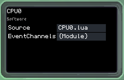
You can set the Source and EventChannels properties from the Multitool while editing your gadget to set these values without using code.
Decoration
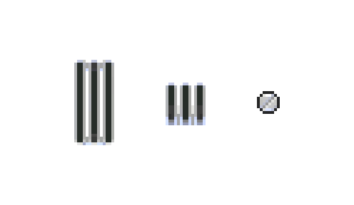
The Decoration modules can be used to give your gadget a little bit of flourish. They have no function other than cosmetics.
Note that the grill decorations need to be picked up from the edges, if you're having trouble moving them.
FlashMemory
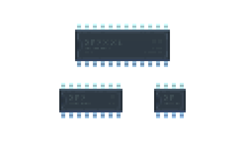
The FlashMemory module allows you to store persistent data while your gadget is powered off or even put away while you're not playing Retro Gadgets.
Sizes
FlashMemory modules have a capacity for how much data they can store, and each different chip size has a different capacity:
 The small FlashMemory can store 4096 bytes.
 The medium FlashMemory can store 32768 bytes.
 The large FlashMemory can store 256000 bytes.
Properties
Returns the overall capacity of the memory in bytes.
Returns the amount of data in bytes currently stored.
Methods
Saves
tableinto the flash memory. Returnstrueif saving was successful,falseotherwise.
Returns the table stored in the memory.
Examples
To store data in a FlashMemory, your data must be in the form of a table.
If you want to store a default number value of 100, for example:
-- first we check if the flash is empty, meaning there is no data in it yet
-- this way we can store something default only if there isn't already saved data
local value = 100

if gdt.FlashMemory0.Usage == 0 then
	-- we put the value we want to store into a table
	-- constructing the table like so gives it a "value" key
	local data = {
		value = value
	}

	gdt.FlashMemory0:Save(data)
end
Once the gadget starts, it will check if there is already data saved in the FlashMemory. If there isn't it'll create a data table with a key value containing our value of 100, and save it.
We can then retrieve the same table that is in the FlashMemory again:
local data = gdt.FlashMemory0:Load()

-- this assumes your data table was given a "value" key
-- otherwise you can index it like any other table by numerical index: data[1]
log(tostring(data.value))
GamepadChip
The GamepadChip allows you to control your gadgets using your computer's real game controller.
Similar in functionality to the Keyboard chip.
Properties
Setting this property allows you to select which one of the gamepads currently connected to your computer the chip will use.
Returns whether or not the selected gamepad is currently active (plugged in and available) on your computer.
Methods
GetButton( name InputName ) InputSource
Returns an InputSource for a given button.
GetAxis( name InputName ) InputSource
Returns an InputSource axis for a given axis.
GetButtonAxis( negativeName InputName, positiveName InputName ) InputSource
Returns an InputSource axis controlled by two given buttons, one for negative and one for positive values.
Events
GamepadChipIsActiveEvent : { IsActive boolean, Type string }
Triggered when a gamepad becomes active or inactive.
*IsActivereturns whether or not the selected gamepad currently became active.
*Typeis"GamepadChipIsActiveEvent".
GamepadChipButtonEvent : { ButtonDown boolean, ButtonUp boolean, IsAxis boolean, InputName InputName, Type string }
Triggered when a gamepad control is pressed or released.
*ButtonDownistrueif a button or axis was pressed at this event.
*ButtonUpistrueif a button or axis was released at this event.
*IsAxisistrueif the input that triggered this event is an axis.
*InputNamereturns the input name of the key that triggered this event.
*Typeis"GamepadChipButtonEvent".
Input names
The following inputs can be used as axis, that is, they return analog values ranging from -100 to 100.
GamepadChip.LeftStickXGamepadChip.LeftStickYGamepadChip.RightStickXGamepadChip.RightStickY
The following inputs can be used as buttons, that is, they can be pressed or released.
GamepadChip.ActionBottomRow1GamepadChip.ActionBottomRow2GamepadChip.ActionBottomRow3GamepadChip.ActionTopRow1GamepadChip.ActionTopRow2GamepadChip.ActionTopRow3GamepadChip.LeftShoulder1GamepadChip.LeftShoulder2GamepadChip.RightShoulder1GamepadChip.RightShoulder2GamepadChip.Center1GamepadChip.Center2GamepadChip.Center3GamepadChip.LeftStickButtonGamepadChip.RightStickButtonGamepadChip.DPadUpGamepadChip.DPadRightGamepadChip.DPadDownGamepadChip.DPadLeft
KeyboardChip
The KeyboardChip allows you to control your gadgets using your computer's real keyboard.
Similar in functionality to the Gamepad chip.
Methods
GetButton( name InputName ) InputSource
Returns an InputSource for a given key.
GetButtonAxis( negativeName InputName, positiveName InputName ) InputSource
Returns an InputSource axis controlled by two given keys, one for negative and one for positive values.
Events
KeyboardChipEvent : { ButtonDown boolean, ButtonUp boolean, InputName InputName, Type string }
Triggered when a key is pressed or released.
*ButtonDownistrueif a key was pressed at this event.
*ButtonUpistrueif a key was released at this event.
*InputNamereturns the input name of the key that triggered this event.
*Typeis"KeyboardChipEvent".
Input names
KeyboardChip.ReturnKeyboardChip.SpaceKeyboardChip.LeftArrowKeyboardChip.RightArrowKeyboardChip.DownArrowKeyboardChip.UpArrowKeyboardChip.BackspaceKeyboardChip.EscapeKeyboardChip.TabKeyboardChip.ClearKeyboardChip.PauseKeyboardChip.ExclaimKeyboardChip.DoubleQuoteKeyboardChip.HashKeyboardChip.DollarKeyboardChip.PercentKeyboardChip.AmpersandKeyboardChip.QuoteKeyboardChip.LeftParenKeyboardChip.RightParenKeyboardChip.AsteriskKeyboardChip.PlusKeyboardChip.CommaKeyboardChip.MinusKeyboardChip.PeriodKeyboardChip.SlashKeyboardChip.Alpha0KeyboardChip.Alpha1KeyboardChip.Alpha2KeyboardChip.Alpha3KeyboardChip.Alpha4KeyboardChip.Alpha5KeyboardChip.Alpha6KeyboardChip.Alpha7KeyboardChip.Alpha8KeyboardChip.Alpha9KeyboardChip.ColonKeyboardChip.SemicolonKeyboardChip.LessKeyboardChip.EqualsKeyboardChip.GreaterKeyboardChip.QuestionKeyboardChip.AtKeyboardChip.LeftBracketKeyboardChip.BackslashKeyboardChip.RightBracketKeyboardChip.CaretKeyboardChip.UnderscoreKeyboardChip.BackQuoteKeyboardChip.AKeyboardChip.BKeyboardChip.CKeyboardChip.DKeyboardChip.EKeyboardChip.FKeyboardChip.GKeyboardChip.HKeyboardChip.IKeyboardChip.JKeyboardChip.KKeyboardChip.LKeyboardChip.MKeyboardChip.NKeyboardChip.OKeyboardChip.PKeyboardChip.QKeyboardChip.RKeyboardChip.SKeyboardChip.TKeyboardChip.UKeyboardChip.VKeyboardChip.WKeyboardChip.XKeyboardChip.YKeyboardChip.ZKeyboardChip.LeftCurlyBracketKeyboardChip.PipeKeyboardChip.RightCurlyBracketKeyboardChip.TildeKeyboardChip.DeleteKeyboardChip.Keypad0KeyboardChip.Keypad1KeyboardChip.Keypad2KeyboardChip.Keypad3KeyboardChip.Keypad4KeyboardChip.Keypad5KeyboardChip.Keypad6KeyboardChip.Keypad7KeyboardChip.Keypad8KeyboardChip.Keypad9KeyboardChip.KeypadPeriodKeyboardChip.KeypadDivideKeyboardChip.KeypadMultiplyKeyboardChip.KeypadMinusKeyboardChip.KeypadPlusKeyboardChip.KeypadEnterKeyboardChip.KeypadEqualsKeyboardChip.InsertKeyboardChip.HomeKeyboardChip.EndKeyboardChip.PageUpKeyboardChip.PageDownKeyboardChip.F1KeyboardChip.F2KeyboardChip.F3KeyboardChip.F4KeyboardChip.F5KeyboardChip.F6KeyboardChip.F7KeyboardChip.F8KeyboardChip.F9KeyboardChip.F10KeyboardChip.F11KeyboardChip.F12KeyboardChip.F13KeyboardChip.F14KeyboardChip.F15KeyboardChip.NumlockKeyboardChip.CapsLockKeyboardChip.ScrollLockKeyboardChip.RightShiftKeyboardChip.LeftShiftKeyboardChip.RightControlKeyboardChip.LeftControlKeyboardChip.RightAltKeyboardChip.LeftAltKeyboardChip.RightCommandKeyboardChip.LeftCommandKeyboardChip.AltGrKeyboardChip.HelpKeyboardChip.PrintKeyboardChip.SysReqKeyboardChip.BreakKeyboardChip.Menu
MagneticConnector
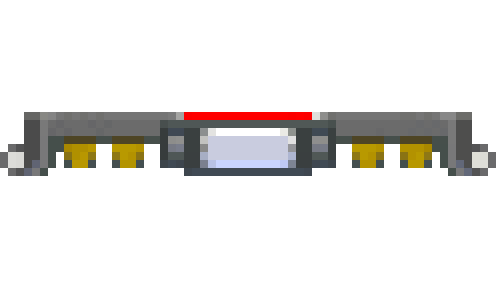
The MagneticConnector can be used to attach different parts of your gadget together. Once two connectors are attached, you can press the button in the middle of them to detach them.
Properties
ButtonState boolean read only
Reflect the pressed/released state of the connector's button.
IsConnected boolean read only
Returns
trueif the connector is connected to another one,falseotherwise.
AttachedConnector MagneticConnector read only
Returns the other MagneticConnector module that this one is attached to, if any.
Events
MagneticConnectorEvent : { IsConnected boolean, Type string }
Triggered once another MagneticConnector attaches or detaches from this one.
*IsConnectedistrueif another connector is attached.
*Typeis"MagneticConnectorEvent".
PowerButton
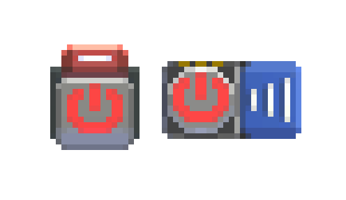
The PowerButton turns your gadget on or off. You must have a PowerButton in your gadget for it to work, and you can only have one at a time. There are different designs of Power buttons, so you need to move it (using the striped handle) into the modules drawers to pick a different one. PowerButtons with blue handles can only go in the middle of your gadgets, while ones with red handles can only go on the edges of your gadget.
Note: Since you can only have one PowerButton per gadget, it will not have a number after its name in your gadget's list of modules:
gdt.PowerButton
Properties
ButtonState boolean read only
Currently only returns
false, pressing down the PowerButton will always toggle the running status of your Gadget.
RealityChip
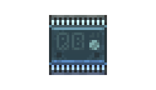
The RealityChip lets you read some values about real-world usage of your computer from inside Retro Gadgets.
Properties
Cpu.TotalUsage number read only
The total CPU usage of the system, from 0 to 100.
Cpu.CoresUsage {number} read only
An array that contains the CPU usage of each logical CPU core, from 0 to 100.
Ram.Available number read only
Available RAM expressed in MB.
Used RAM expressed in MB.
Network.TotalSent number read only
Total sent by network interfaces expressed in Mbps.
Network.TotalReceived number read only
Total received from network interfaces expressed in Mbps.
LoadedAssets Asset read only
Array containing all the assets currently loaded from the
Documents/My Games/Retro/UserDatafolder.
Methods
GetDateTime( ) {}
Returns a table containing the current local date and time.
The values in the table are:
*year
*month
*day
*yday(year day)
*wday(week day)
*hour
*min
*sec
*isdst(is daylight saving time)
GetDateTimeUTC( ) {}
Returns a table containing the current local date and time expressed as the Coordinated Universal Time (UTC).
The values in the table are:
*year
*month
*day
*yday(year day)
*wday(week day)
*hour
*min
*sec
*isdst(is daylight saving time)
LoadAudioSample( filename string ) AudioSample
Load an AudioSample asset from an audio file.
The file must be inDocuments/My Games/Retro/UserData,filenamerepresents the relative path.
LoadSpriteSheet( filename string, spritesWidth number, spritesHeight number ) SpriteSheet
Load a SpriteSheet asset from an image file.
The file must be inDocuments/My Games/Retro/UserData,filenamerepresents the relative path.
UnloadAsset( filename string )
Unload a previously loaded asset.
Remove it fromLoadedAssetsand make it invalid.
ListDirectory( directory string ) string[]
Returns the list of files and folders contained in the specified folder.
The directory must be inDocuments/My Games/Retro/UserData, thedirectoryparameter represents the relative path.
GetFileMetadata( filename string ) {}
Returns a table containing information about the file without the need to load it.
The file must be inDocuments/My Games/Retro/UserData,filenamerepresents the relative path.
ROM
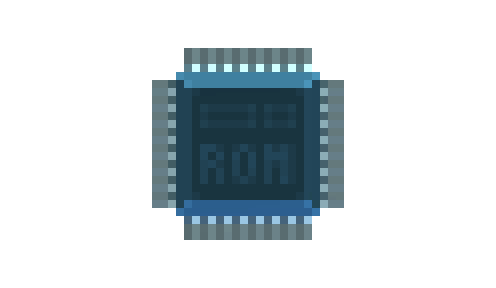
The ROM chip gives you access to assets through code. These include some built-in assets such as the StandardFont.
Note: Since you can only have one ROM per gadget, it will not have a number after its name in your gadget's list of modules:
gdt.ROM
Properties
ROM contains two main properties, User and System. User gives you access to your own assets added to your gadget through the Multitool, and System accesses the built-in assets. Each one of those two properties have their own tables as such:
Returns a table of all assets regardless of type.
SpriteSheets {SpriteSheet} read only
Returns a table of only SpriteSheets.
Returns a table of only Code assets.
AudioSamples {AudioSample} read only
Returns a table of only AudioSamples.
Examples
Say you have a sprite sheet in your gadget's assets named "Player.png" which contains sprites for a player character. To use it with the VideoChip's DrawSprite method, you would load it like so:
local sheet = gdt.ROM.User.SpriteSheets["Player.png"]

gdt.VideoChip0:DrawSprite(vec2(10,10), sheet, 0, 0, color.white, color.clear)
In this case we are drawing the sprite at the requested SpriteSheet sheet's position 0, 0 onto the Screen position 10, 10, without affecting its tint or transparency.
If you want to print text using the default font, you need to load it like so:
local font = gdt.ROM.System.SpriteSheets["StandardFont"]

gdt.VideoChip0:DrawText(vec2(10,10), font, "Hello world!", color.white, color.clear)
This will use the StandardFont to print the string "Hello world!" at the screen's position 10, 10, in white color and no background. If you want to make a custom font to use with this function instead, check the font function of the Sprite Editor.
SecurityChip
The security chip makes it so your gadget's assets and code cannot be inspected or exported by other players when you publish your gadget on the Workshop. Once you include it in your gadget, each one of your assets will have an icon next to it to deny (red lock) or allow (green eye) access by people inspecting your gadget.
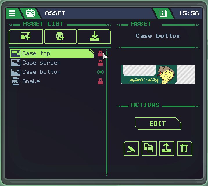
Note: Since you can only have one SecurityChip per gadget, it will not have a number after its name in your gadget's list of modules:
gdt.SecurityChip
However, there is currently no code that uses the SecurityChip.
VideoChip
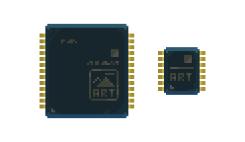
The VideoChip controls Screens and ScreenButtons to display graphics on them using SpriteSheets.
Sizes
There are three different VideoChip sizes, but currently their behavior is identical.
Properties
The buffering mode for this VideoChip. Defaults to
DoubleBuffer.
Width in pixels of the rendering buffer. The area takes into account all the displays connected to this VideoChip.
Height in pixels of the rendering buffer. The area takes into account all the displays connected to this VideoChip.
RenderBuffers {RenderBuffer} read only
List of RenderBuffers on which the VideoChip can render.
TouchState boolean read only
The pressed/released state of the screen touch interaction.
A boolean flag that will only be set to true during the time tick in which the TouchState changes from released to pressed.
A boolean flag that will only be set to true during the time tick in which the TouchState changes from pressed to released.
TouchPosition vec2 read only
The position of the touch interaction on the screen area.
Methods
This method sets the VideoChip to use screens as render targets.
RenderOnBuffer( index number )
This method sets the VideoChip to use one of its RenderBuffers as a render target.
Theindexparameter identifies the RenderBuffer to use.
SetRenderBufferSize( index number, width number, height number )
Resize one of the VideoChip's RenderBuffers.
Clears all the render area with the specified
color
SetPixel( position vec2, color color )
Sets the pixel at the specified
positionto the specifiedcolor
DrawPointGrid( gridOffset vec2, dotsDistance number, color color )
Draws a dotted grid on the entire display area, with an offset. The
dotsDistanceparameter express the distance in pixels, on both axis, between dots.
DrawLine( start vec2, end vec2, color color )
Draws a line from position
startto positionend, using the specifiedcolor
DrawCircle( position vec2, radius number, color color )
Draws an empty circle at the specified
position, with the specifiedradius, in the specifiedcolor.
FillCircle( position vec2, radius number, color color )
Draws a filled circle at the specified
position, with the specifiedradius, in the specifiedcolor.
DrawRect( position1 vec2, position2 vec2, color color )
Draws an empty rect from
position1toposition2, in the specifiedcolor.
FillRect( position1 vec2, position2 vec2, color color )
Draws a filled rect from
position1toposition2, in the specifiedcolor.
DrawTriangle( position1 vec2, position2 vec2, position3 vec2, color color )
Draws an empty triangle with vertexes in
position1,position2andposition3, in the specifiedcolor.
FillTriangle( position1 vec2, position2 vec2, position3 vec2, color color )
Draws a filled triangle with vertexes in
position1,position2andposition3, in the specifiedcolor.
DrawSprite( position vec2, spriteSheet SpriteSheet, spriteX number, spriteY number, tintColor color, backgroundColor color )
Draws a specific sprite frame from the
spriteSheet.
Position is the on-screen sprite desiredpositionstarting from the top left corner,spriteSheetis the SpriteSheet asset containing the sprite frame to draw,spriteXandspriteYare the coordinates to identify the desired sprite frame starting from the, top left corner, expressed in grid units.spriteX=0 andspriteY=0 are the coordinates of the first sprite, top left.tintColoris the color multiplier used to draw the sprite frame.Color(255,255,255)orcolor.whitewill leave the sprite frame unaffected.backgroundColoris the color used to replace the transparent areas of the spriteFrame. UsingColorRGBA(0,0,0,0)orcolor.clearwill leave the transparency as it is.
DrawCustomSprite( position vec2, spriteSheet SpriteSheet, spriteOffset vec2, spriteSize vec2, tintColor color, backgroundColor color )
Draw a portion of a SpriteSheet (defined by
spriteOffset,spriteSize) without taking into account the grid
DrawText( position vec2, fontSprite SpriteSheet, text string, textColor color, backgroundColor color )
Draws the string contained in the
textparameter, at the desiredposition, usingtextColorandbackgroundColor.
The parameterfontSpriteexpect a spriteSheet asset labeled as font.
By placing a ROM you can access the standard font:gdt.ROM.System.SpriteSheets["StandardFont"]
RasterSprite( position1 vec2, position2 vec2, position3 vec2, position4 vec2, spriteSheet SpriteSheet, spriteX number, spriteY number, tintColor color, backgroundColor color )
Draws a specific sprite frame from the
spriteSheetmapping it on a quad identified byposition1,position2,position3,position4
RasterCustomSprite( position1 vec2, position2 vec2, position3 vec2, position4 vec2, spriteSheet SpriteSheet, spriteOffset vec2, spriteSize vec2, tintColor color, backgroundColor color )
Draws a portion of a SpriteSheet (defined by
spriteOffset,spriteSize) without taking into account the grid mapping it on a quad identified byposition1,position2,position3,position4
DrawRenderBuffer( position vec2, renderBuffer RenderBuffer, width number, height number )
Draws a render buffer (supposedly coming from Webcam component) at the desired
position,widthandheight
DrawCustomRenderBuffer( position vec2, renderBuffer RenderBuffer, width number, height number, bufferAreaOffset vec2, bufferAreaSize vec2 )
Draws a portion of a renderBuffer (defined by
bufferAreaOffsetandbufferAreaSize)
RasterRenderBuffer( position1 vec2, position2 vec2, position3 vec2, position4 vec2, renderBuffer RenderBuffer )
Draws a RenderBuffer mapping it on a quad identified by
position1,position2,position3,position4.
RasterCustomRenderBuffer( position1 vec2, position2 vec2, position3 vec2, position4 vec2, renderBuffer RenderBuffer, bufferAreaOffset vec2, bufferAreaSize vec2 )
Draws a portion of a RenderBuffer (defined by
bufferAreaOffset,bufferAreaSize) without taking into account the grid mapping it on a quad identified byposition1,position2,position3,position4
SetPixelData( pixelData PixelData )
Apply
pixelDatacontent to VideoChip's video buffer, width and height must have the same value as VideoChip's
BlitPixelData( position vec2, pixelData PixelData )
Draw a
pixelDatacontent to VideoChip's video buffer at the offset ofposition. This way PixelData width and height don't need to match the VideoChip's
Events
VideoChipTouchEvent : { TouchDown boolean, TouchUp boolean, Value vec2, Type string }
Sent when the touch interaction is pressed or released.
Buffering modes
There are two valid values for a VideoChipMode:
SingleBufferDoubleBuffer
Double buffering means the video chip will flip between two buffers instead of constantly refreshing the same one. This is a technique to prevent image tearing, since with two buffers you don't see the current active one being drawn to. In practice, use whichever mode seems to work best in your gadget.
Wifi
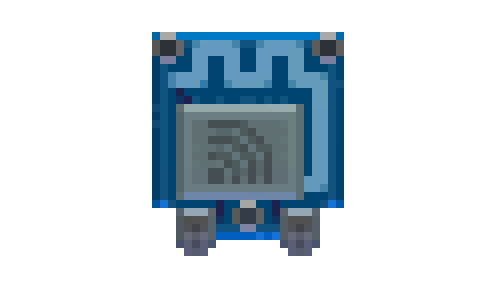
Properties
AccessDenied boolean read only
Will return
trueif network access is denied. See Permissions for more information.
AudioStreams {AudioSample} read only
Table containing the active audio streams. The key of the table is the connection handle.
Methods
Send a web HTTP GET request, return a numeric handle to identify the request
WebPutData( url string, data string ) number
Send a web HTTP PUT request, return a numeric handle to identify the request
WebPostData( url string, data string ) number
Send a web HTTP POST request, return a numeric handle to identify the request
WebPostForm( url string, form table ) number
Send a web HTTP POST request, return a numeric handle to identify the request
WebCustomRequest( url string, method string, customHeaderFields table, contentType string, contentData string ) number
Send a web request, return a numeric handle to identify the request
WebGetAudioStream( url string ) number
Opens a web audio stream, return a numeric identifier to identify the request
WebAbort( handle number ) boolean
Abort a web request
GetWebUploadProgress( handle number ) number
Returns a percentage (0-100) representing the progress of the current upload associated with the given handle
GetWebDownloadProgress( handle number ) number
Returns a percentage (0-100) representing the progress of the current download associated with the given handle
Clear stored cookies
ClearUrlCookieCache( url string )
Only cookies that apply to this
urlwill be removed from the cache
Events
WifiWebResponseEvent : { Url string, RequestHandle number, ResponseCode number, IsError boolean, ErrorType string, ErrorMessage string, ContentType string, Text string, Data string, AudioSample AudioSample, PixelData PixelData, Type string }
Sent when a web request is completed by the remote server.
*Urlthe url of the request
*RequestHandleis the handle of the request, which matches the number returned by the function that initiated it.
*ResponseCodeis the HTTP code returned by the server.
*IsErroris a boolean value which indicates if the response wasn't successful.
*ErrorTypeandErrorMessageelaborate on the error encountered by the request.
*ContentTypeis the MIME type of the content the server returned.
*Textis the UTF8 encoded content of the response.
*Datais the binary content of the response.
*AudioSampleis the streaming AudioSample (only when usingWebGetAudioStream(url)).
*PixelDataif the response contains an image, this field contains the decoded data.
*Typeis"WifiWebResponseEvent".
Examples
When making a web request to a URL, the request function will give you only a handle to keep track of said request. To get the actual response from the server, since it's an asynchronous process, we need to use an event. Here is an example which uses World Time API to get information about the current time in the London timezone:
gdt.Wifi0:WebGet("http://worldtimeapi.org/api/timezone/Europe/London.txt")

function eventChannel1(sender, response)
	if response.IsError == false then
		log(response.Text)
	end
end
The call to WebGet, outside of the update function, will run only once when the gadget is powered on. Then, once the server is done replying to us, the eventChannel1 function will trigger. If our response is not an error code, the text content of the response will be shown in the Multitool debug screen.
Note: In order for this example to work, your WiFi module must be set on your CPU's event channel 1, and you must enable network permissions for your gadget.
Serial
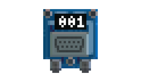
Module that allows communication through the serial port.
Properties
Determines the type of data received by the SerialReceiveEvent event.
The BinaryData option passes binary data into the event's Data property.
The Lines option splits the received data into lines using the \n character as a separator, writing the result inside the event's Lines property.
Serial COM port number.
Indicates if the serial connection on the specified port is active.
The serial connection baud rate.
The standard length of data bits per byte.
The value must be between 5 and 8 inclusive.
The serial connection parity-checking protocol.
The number of stopbits per byte.
Methods
Writes an 8-bit integer to the serial port.
WriteUInt8( value number )
Writes an 8-bit unsigned integer to the serial port.
WriteInt16( value number )
Writes a 16-bit integer to the serial port.
WriteUInt16( value number )
Writes a 16-bit unsigned integer to the serial port.
WriteInt32( value number )
Writes a 32-bit integer to the serial port.
WriteUInt32( value number )
Writes a 32-bit unsigned integer to the serial port.
WriteFloat32( value number )
Writes a 32-bit float to the serial port.
WriteFloat64( value number )
Writes a 64-bit float to the serial port.
Writes a byte array to the serial port.
Write a utf8 string to the serial port.
Writes a string with a \n (new line) added at the end to the serial port.
Returns an array containing the available serial COM port numbers.
Events
SerialIsActiveEvent : { IsActive boolean, Type string }
Sent when the serial IsActive state change.
*IsActiveindicates if the serial connection on the specified port is active.
*Typeis"SerialIsActiveEvent".
SerialReceiveEvent : { Lines {}, Data string, Type string }
Sent when data is received from a Serial module.
The module'sReceiveModeproperty determines the type of data received by the event.
* The SerialReceiveMode.BinaryData option passes binary data into theDataproperty.
* The SerialReceiveMode.Lines option splits the received data into lines using the\ncharacter as a separator, writing the result inside theLinesproperty.
*Typeis"SerialReceiveEvent".
Receive modes
There are two valid values for a SerialReceiveMode:
BinaryDataLines
The BinaryData option passes binary data into the event's Data property, the Lines option splits the received data into lines using the \n character as a separator, writing the result inside the event's Lines property.
Parity
SerialParity specifies the parity bit mode:
NoneNo parity check occurs.OddSets the parity bit so that the count of bits set is an odd number.EvenSets the parity bit so that the count of bits set is an even number.MarkLeaves the parity bit set to 1.SpaceLeaves the parity bit set to 0.
Stop bits
SerialStopBits Specifies the number of stop bits.
OneOne stop bit is used.OnePointFive1.5 stop bits are used.TwoTwo stop bits are used.
Assets
SpriteSheet
A SpriteSheet asset contains images to be used in a gadget, which can be displayed with the VideoChip and Screen, or printed as stickers to decorate the shell of the gadget. You can import PNG images as SpriteSheets in the Multitool or edit them in-game with the Sprite Editor.
To import a SpriteSheet from your computer, the image must be at most 256 x 64 pixels in size, with best results when using "PNG-8" or "Indexed PNG" modes.
Properties
The name of the asset.
String containing
"SpriteSheet"
Returns the palette used in the sprite sheet, which can be seen in the Sprite Editor. Currently, there's no code that can be used with this.
Methods
Returns true if the asset reference is still valid.
References can become invalid if the asset is unloaded.
Returns a PixelData object containing the SpriteSheet data.
GetSpritePixelData( spriteX number, spriteY number ) PixelData
Returns a PixelData object containing the data of a specific sprite. The sprite is identified by
spriteXandspriteYwhich represent its coordinate on the grid.
Code
A Code asset contains the Lua script that will be run by your gadget's CPU. It can be created through the Code Editor in-game, or imported into the assets list.
While you can retrieve a Code asset with the ROM chip, there's currently no methods that use this asset type that way.
AudioSample
An AudioSample is a piece of audio that can be played back from your gadget with the AudioChip module.
To import an AudioSample, you must use OGG, WAV or MP3 files, and for best results they must be 44.1kHz and 16bit.
Currently, there's no way to create an AudioSample purely in-game, but audio generation is planned for the future.
Properties
The name of the asset.
String containing
"AudioSample"
SamplesCount number read only
Length of the AudioSample in seconds
Table that contains the AudioSample's metadata, it can contain the following values:
*LongDescription
*Date
*Year
*TrackNumber
*TrackTotal
*DiscNumber
*DiscTotal
*Popularity
*SeriesPart
*Bitrate
*BitDepth
*SampleRate
*IsVariableBitRate
*Duration
*SeriesTitle
*SortTitle
*Title
*Artist
*Composer
*Comment
*Genre
*Album
*Group
*OriginalArtist
*Copyright
*OriginalAlbum
*Publisher
*PublishingDate
*AlbumArtist
*Conductor
*ProductId
*SortAlbum
*SortAlbumArtist
*SortArtist
*Description
Methods
Returns true if the asset reference is still valid.
References can become invalid if the asset is unloaded.
RenderBuffer
A RenderBuffer is similar to a PixelData, however it can't be modified directly from code.
VideoChips have an array of child RenderBuffers, with the VideoChip.RenderOnBuffer method you can set one as render target allowing you to use draw methods on the selected RenderBuffer.
A RenderBuffer can also be obtained with the Webcam module, to be displayed with VideoChip methods.
Properties
The name of the asset.
String containing
"RenderBuffer"
Width in pixels.
Height in pixels.
Methods
Returns true if the asset reference is still valid.
References can become invalid if the asset is unloaded.
Returns a PixelData object containing the RenderBuffer data.